Cisco ACI Multi-Pod (Pt.1) – IPN (Inter-Pod Network) Configuration & Verification
Inter-Pod Network (IPN) Topology
This post is the first in a three part (part two here) series on configuring Cisco ACI MultiPod and is based upon experiences from a number of multi-pod deployments and the inforssmmation provided is from a live deployment with anonymity changes of course, this is one post of a 3 post series about configuring Cisco ACI MultiPod. The hardware in this deployment consists of Cisco Nexus C9236C switches with NXOS: version 7.0(3)I5(2), using 40G (QSFP-40G-SR-BD) links between the IPN devices and the spine switches and 10G links between the IPN devices using a breakout cable from the QSFP-40G-SR4 optic installed in the IPN devices.
The spine switches are Cisco N9K-C9336PQ spine switches on firmware n9000-13.0(1k) using QSFP-40G-SR-BD optics towards the IPN devices. The APIC firmware version is 3.0(1k).
The following diagram depicts the design of the IPN connectivity showing only the relevant devices for IPN, all other spine and all leaf switches are not shown for brevity.
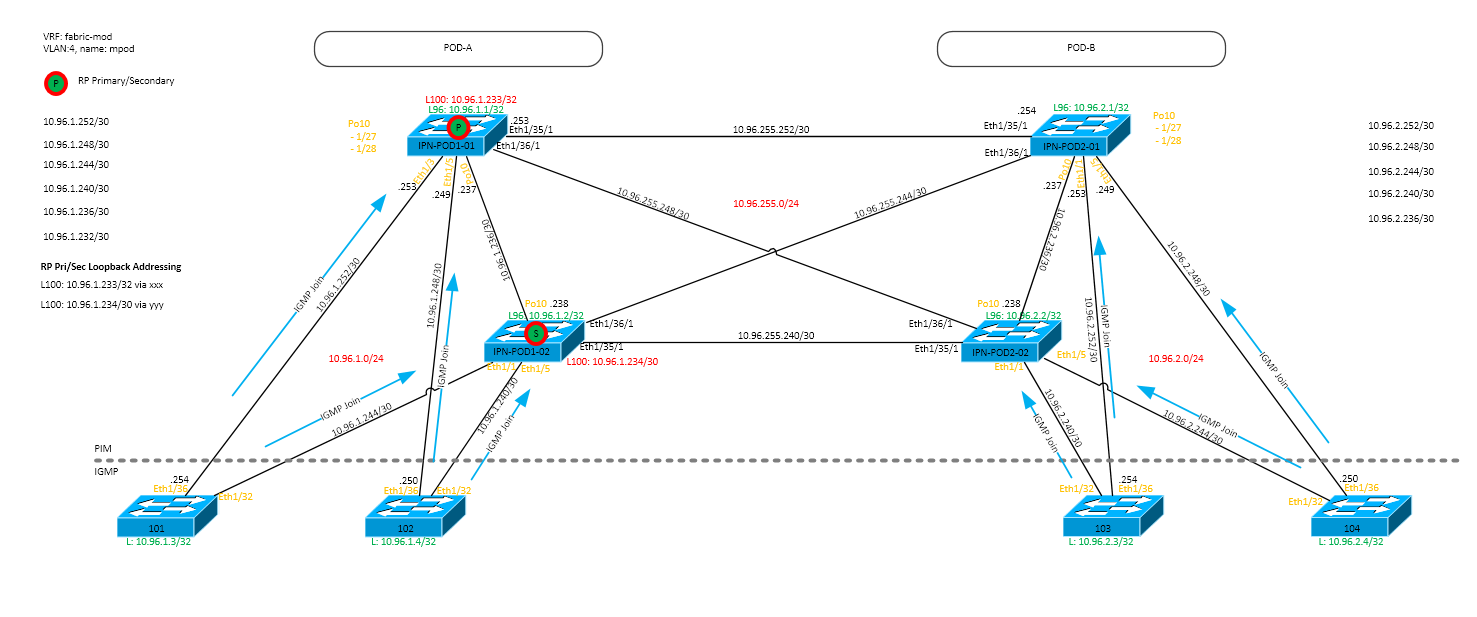
In this deployment, POD-1 and POD-2 happen to be in geographically diverse data centers where the four inter-connecting WAN links are 10Gbps Ethernet each although the POD’s could be in different campus locations or on different floors in a data center.
IPN L2
The only IPN requirements at layer 2 are to use VLAN 4 and increase the MTU. The VLAN requirement is for 802.1q between the spine and the IPN devices and to use encapsulation dot1q 4 on these sub-interfaces, additionally the system and L3 interface MTU must be set to 9150 as follows.
!
system jumbomtu 9150
!
interface Ethernetx...
 desc any interface carrying IPN traffic
 mtu 9150
IPN L3
VRF
We have VRF’s configured on this deployment and this is also a recommended configuration by Cisco though not technically required but is good practice as we want to isolate the IPN traffic from interruption certainly if the IPN devices are used for other services and route table changes could break IPN connectivity. Using VRFs requires all interfaces (or sub-interfaces) including dedicated IPN loopbacks to be in the VRF as well as a separate OSPF process in that VRF. The PIM RP address will be configured in the VRF too and is discussed in the multicast section in this post. The VRF in this deployment is called ‘fabric-mpod’, this VRF is not configured in the APIC, it only exists on the IPN devices encompassing VLAN 4.
vrf context fabric-mpod
!
interface loopback yy
  vrf member fabric-mpod
!
interface Ethernetx...
  vrf member fabric-mpod
!
router ospf a1
  vrf fabric-mpod
Addressing
IP addressing for the WAN and IPN POD to Spine has been taken from a RFC 1918 range, the allocated range has been split in to three class C networks (/24), one each for;
- POD-A IPN [10.96.1.0/24]
- POD-B IPN [10.96.2.0/24]
- WAN Interconnects [10.96.255.0/24]
Within the ACI fabric the IPN uses tenant ‘infra’ and VRF ‘overlay-1’ (translates to the VRF on the IPN devices ‘fabric-mpod’ – you could call the IPN devices VRF ‘overlay-1’ to keep it consistent but I don’t think its very descriptive). The address ranges used should not conflict with any other addressing in the ‘overlay-1’ VRF. The IPN devices have loopback created using host addresses from the start of the allocated pool for the POD they are located in. The loopback addresses on the spine switches are configured via the OSPF configuration on the APIC. Interconnects between the IPN devices and IPN & spine switches are allocated /30 addresses starting at the end of the allocated pool and work backwards for each allocation.
Routing
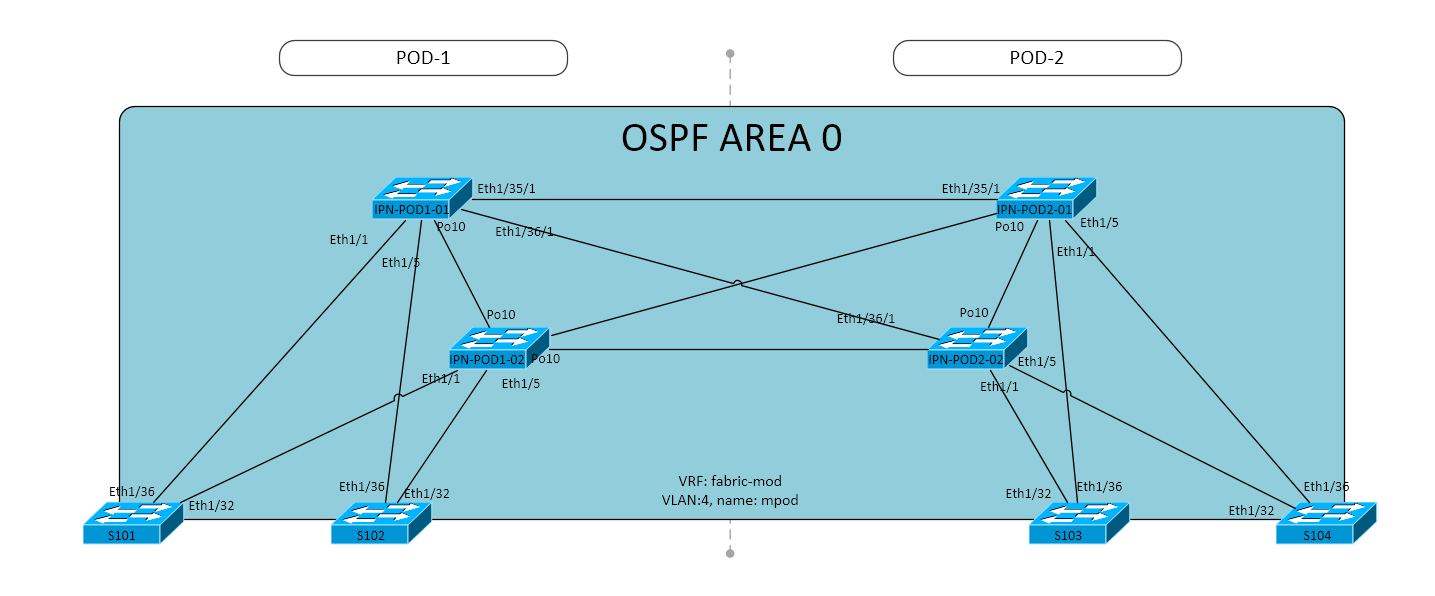
OSPF is used on the IPN between the connected spine switches and IPN devices, also between the IPN devices in all pods. The diagram below shows area 0 being used across the IPN and spine devices. Other OSPF areas can be used but they MUST be configured as ‘normal’ areas, in other words do not configure them as stub or NSSA areas for example.
The links (interfaces) between the IPN devices and the spine switches must have the following OSPF configuration on the interfaces (as discussed, these are actually the sub-interfaces for VLAN-4).
  ip ospf network point-to-point
  ip ospf mtu-ignore
  ip router ospf a1 area 0.0.0.0
As shown in the code snippet, the network type between the IPN device and the spin device must be point to point and ignore MTU must be turned on. These settings are important for these links, for the IPN to IPN links, these can be configured with a network type that is relevant to the … network type ! – this is just normal OSPF configuration here with the above caveats with area type. In addition a dedicated loopback is used for the VRF and the PIM RP. Each IPN device must have this dedicated loopback active in the same OSPF area as the links. The following config shows the loopbacks for a IPN device acting as a primary RP.
interface loopback96
  vrf member fabric-mpod
  ip address 10.96.1.1/32
  ip router ospf a1 area 0.0.0.0
  ip pim sparse-mode

interface loopback100
  desc Dedicated RP Loopback
  vrf member fabric-mpod
  ip address 10.96.1.233/32
  ip router ospf a1 area 0.0.0.0
  ip pim sparse-mode
Multicast
Cisco ACI requires\recommends (works best with) bi-dir multicast as we have many sources and many receivers. Referring to the diagram above, all the links require ‘ip pim sparse-mode‘ configured including the dedicated loopback(s). The VRF itself requires the RP configured for the group 225.0.0/8 which is used by the bridge domains for BUM traffic (discussed in the next section). The 239.255.255.240/28 is used for fabric specific purposes, for example the 239.255.255.240/32 address is used for arp gleaning. The configuration for the RP on a IPN device is shown below, the RP IP address being the IP address on the dedicated loopback in the multi pod VRF.
ip pim mtu 9000
vrf context fabric-mpod
    ip pim rp-address 10.96.1.233 group-list 225.0.0.0/8 bidir
    ip pim rp-address 10.96.1.233 group-list 239.255.255.240/28 bidir
What is important to note is that bi-dir has no native solution for redundancy. To implement redundancy we create use the concept of Redundant Phantom Rendezvous Points, we use the single IP address for the RP configuration on each of the IPN devices as shown above. This configuration is discussed later in this post.
Cisco ACI uses a multicast address per bridge domain to encapsulate BUM traffic to be sent to other TEPs (Leaf Switches) across the fabric. This concept is extended over the IPN for multi pod deployments. If we take a look at an example bridge domain on the APIC which is active in both pods, we see on the “Advanced/Troubleshooting” tab that we have a system assigned multicast address of 225.0.13.224/32 which is unique to this bridge domain.
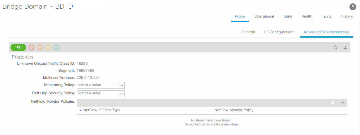
If we want to quickly get a list of all the bridge domains and the assigned multicast addresses, from the APIC CLI use the following command;
moquery -c fvBD | grep 'name\|bcastP'
The spine switches do not support PIM, they use IGMP joins to the connected L3 IPN devices as a host or L2 switch would. This is important to note as you need to be sure your IPN design does not have IPN devices forwarding PIM joins to the RP through the spine switches. As the spine switches do not run PIM they will drop the PIM requests and break multicast. An example of this design issue is where redundant IPN devices are used in both PODs and the local IPN devices connected to the spine switches do not have a PIM enabled path between them locally or towards the RP. It is possible to fix this with OSPF costs but you would have hair-pinning of PIM joins and multicast data over your WAN – not very efficient ! The following diagram explains the issue.

The preceding design shows the problem in that there are no links and/or local PIM enabled paths between the local IPN devices. This causes multicast to break. When POD-1 S102 sends an IGMP Join to IPN-POD1-02, IPN-POD1-02 converts this to a PIM Join and sends to its configured RP (IPN-POD1-01). IPN-POD1-02 looks in its route table and finds the best way is via POD-1 S101 spine switch, it sends the PIM join towards the S101 switch. When the S101 switch receives this PIM Join it drops it because the spine switches only run IGMP not PIM. (All OSPF interface costs are default, IPN WAN are 10G, IPN-SPINE are 40G links)
The IPN-POD1-02 device is not informed of the PIM drop by the spine switch and therefore installs multicast routes in the mroute table to send and receive multicast packets for the (*,G) over the link to S101. No multicast traffic will be received over the S101->IPN-POD1-02 link as the IGMP join on the IPN device is from spine S102. This could be solved by changing OSPF costs but the same issue would occur during certain failure scenarios or traffic would hairpin through POD-2.
Examples of ARPs from Host-A for Host-B, the multicast encapsulated ARP would get as far as S101 (S102>>IPN-POD1-02>>S102) and be dropped by S102. For ARPs from Host-B for Host-A, the multicast encapsulated ARP would be sent from POD-2 from S104>>IPN-POD2-01>>IPN-POD1-01[RP] which is correct, but there are no PIM joins on this path from POD-1 as they were dropped at S101.
Validation
We should have the APIC configured with multipod and a L3Out which enables the spine interfaces configured to actively sending IGMP joins for bridge domain multicast addresses. So to validate the operation lets check to see we have the expected IGMP Joins from the spine switches to the directly connected IXN devices. We will look for a particular join on 225.0.13.224 as we saw in the APIC bridge domain (shown previously) advanced section of the GUI. The ACI fabric will only send one join in each POD for each multicast address so look on all directly connected IXN devices to spines.
Cisco CCO document states the selection of the spine node and link to send the IGMP as;
“For each Bridge Domain, one spine node is elected as the authoritative device to perform both functions described above (the IS-IS control plane between the spines is used to perform this election). the elected spine will select a specific physical link connecting to the IPN devices to be used to send out the IGMP join (hence to receive multicast traffic originated by a remote leaf) and for forwarding multicast traffic originated inside the local Pod.”
Looking at the output from the POD-1 & POD-2 spine devices on vlan-4 which is the vlan used by multi-pod on the fabric.
- In POD-1 we find the IGMP Join from S102 to IPN-POD1-02 device
- In POD-2 we find the IGMP Join from S104 to IPN-POD2-01 device
Spine switches S101 & S102 are in POD-1 and S103 & S104 are in POD-2 as shown in the first diagram in this post. We can validate the device the join is sent to by looking at the outbound interface and checking against the diagram and/or as shown in the next section where we will be looking at the IPN devices IGMP Joins received.
Spine Switch IGMP Join
S101# show ip igmp gipo joins
GIPo list as read from IGMP-IF group-linked list
------------------------------------------------
GIPo Addr         Source Addr       Join/Leave  Interface           Iod       Enable/Disable
225.0.59.64       0.0.0.0           Join        Eth1/36.42          76        Enabled
225.0.238.32      0.0.0.0           Join        Eth1/36.42          76        Enabled
239.255.255.240   0.0.0.0           Join        Eth1/36.42          76        Enabled

S102# show ip igmp gipo joins
GIPo list as read from IGMP-IF group-linked list
------------------------------------------------
GIPo Addr         Source Addr       Join/Leave  Interface           Iod       Enable/Disable
225.0.0.0         0.0.0.0           Join        Eth1/36.43          76        Enabled
225.0.87.176      0.0.0.0           Join        Eth1/36.43          76        Enabled
225.0.156.48      0.0.0.0           Join        Eth1/36.43          76        Enabled
225.0.174.32      0.0.0.0           Join        Eth1/36.43          76        Enabled
225.1.34.64       0.0.0.0           Join        Eth1/36.43          76        Enabled
225.1.142.160     0.0.0.0           Join        Eth1/36.43          76        Enabled
225.0.13.224      0.0.0.0           Join        Eth1/32.32          72        Enabled
225.0.149.0       0.0.0.0           Join        Eth1/32.32          72        Enabled
225.1.60.208      0.0.0.0           Join        Eth1/32.32          72        Enabled

S103# show ip igmp gipo join
GIPo list as read from IGMP-IF group-linked list
------------------------------------------------
GIPo Addr         Source Addr       Join/Leave  Interface           Iod       Enable/Disable
225.0.0.0         0.0.0.0           Join        Eth1/32.47          72        Enabled
225.0.59.64       0.0.0.0           Join        Eth1/32.47          72        Enabled
225.1.142.160     0.0.0.0           Join        Eth1/32.47          72        Enabled
239.255.255.240   0.0.0.0           Join        Eth1/32.47          72        Enabled

S104# show ip igmp gipo joins
GIPo list as read from IGMP-IF group-linked list
------------------------------------------------
GIPo Addr         Source Addr       Join/Leave  Interface           Iod       Enable/Disable
225.0.87.176      0.0.0.0           Join        Eth1/32.32          72        Enabled
225.0.156.48      0.0.0.0           Join        Eth1/32.32          72        Enabled
225.0.174.32      0.0.0.0           Join        Eth1/32.32          72        Enabled
225.0.238.32      0.0.0.0           Join        Eth1/32.32          72        Enabled
225.1.34.64       0.0.0.0           Join        Eth1/32.32          72        Enabled
225.0.13.224      0.0.0.0           Join        Eth1/36.47          76        Enabled
225.0.149.0       0.0.0.0           Join        Eth1/36.47          76        Enabled
225.1.60.208      0.0.0.0           Join        Eth1/36.47          76        Enabled
Now we have confirmed there are IGMP Joins being sent towards the IPN devices from the ACI fabric spine switches, we check each directly connected IPN device for IGMP joins. The following output is from each of the directly connected IPN devices. Again we can check any bridge domain multicast address. In this case we are looking for 225.0.13.224, this should be present on one of each of the IPN devices in each connected POD. We see (as we expected) that IPN-POD1-02 has an IGMP join from the fabric spine 102 and IPN-POD2-01 has an IGMP join from fabric spine 104 in POD2. Notice we have IGMP joins across all switches and IPN connected interfaces in each POD showing some type of load sharing. We can check the source of the IGMP Join from the received interface and/or the Last Reporter in the output being the spine l3 interface address.
IPN-POD1-01# sh ip igmp groups vrf fabric-mpod
IGMP Connected Group Membership for VRF "fabric-mpod" - 9 total entries
Type: S - Static, D - Dynamic, L - Local, T - SSM Translated
Group Address      Type Interface           Uptime    Expires   Last Reporter
225.0.0.0          D    Ethernet1/5.4       1w4d      00:02:27  10.96.1.250
225.0.59.64        D    Ethernet1/1.4       3d05h     00:03:37  10.96.1.254
225.0.87.176       D    Ethernet1/5.4       1d08h     00:02:26  10.96.1.250
225.0.156.48       D    Ethernet1/5.4       3d00h     00:02:27  10.96.1.250
225.0.174.32       D    Ethernet1/5.4       1d08h     00:02:26  10.96.1.250
225.0.238.32       D    Ethernet1/1.4       3d05h     00:03:37  10.96.1.254
225.1.34.64        D    Ethernet1/5.4       3d05h     00:02:27  10.96.1.250
225.1.142.160      D    Ethernet1/5.4       3d05h     00:02:27  10.96.1.250
239.255.255.240    D    Ethernet1/1.4       1w4d      00:03:37  10.96.1.254

IPN-POD1-02# sh ip igmp groups vrf fabric-mpod
IGMP Connected Group Membership for VRF "fabric-mpod" - 3 total entries
Type: S - Static, D - Dynamic, L - Local, T - SSM Translated
Group Address      Type Interface           Uptime    Expires   Last Reporter
225.0.13.224       D    Ethernet1/5.4       04:07:57  00:04:19  10.96.1.242
225.0.149.0        D    Ethernet1/5.4       04:07:57  00:04:19  10.96.1.242
225.1.60.208       D    Ethernet1/5.4       04:07:57  00:04:19  10.96.1.242

IPN-POD2-01# sh ip igmp groups vrf fabric-mpod
IGMP Connected Group Membership for VRF "fabric-mpod" - 3 total entries
Type: S - Static, D - Dynamic, L - Local, T - SSM Translated
Group Address      Type Interface           Uptime    Expires   Last Reporter
225.0.13.224       D    Ethernet1/5.4       04:27:15  00:03:23  10.96.2.250
225.0.149.0        D    Ethernet1/5.4       04:27:14  00:03:23  10.96.2.250
225.1.60.208       D    Ethernet1/5.4       04:27:13  00:03:22  10.96.2.250

IPN-POD2-02# sh ip igmp gr vrf fabric-mpod
IGMP Connected Group Membership for VRF "fabric-mpod" - 9 total entries
Type: S - Static, D - Dynamic, L - Local, T - SSM Translated
Group Address      Type Interface           Uptime    Expires   Last Reporter
225.0.0.0          D    Ethernet1/1.4       04:10:29  00:04:16  10.96.2.242
225.0.59.64        D    Ethernet1/1.4       04:10:29  00:04:16  10.96.2.242
225.0.87.176       D    Ethernet1/5.4       04:10:29  00:02:49  10.96.2.246
225.0.156.48       D    Ethernet1/5.4       04:10:29  00:02:49  10.96.2.246
225.0.174.32       D    Ethernet1/5.4       04:10:29  00:02:49  10.96.2.246
225.0.238.32       D    Ethernet1/5.4       04:10:29  00:02:48  10.96.2.246
225.1.34.64        D    Ethernet1/5.4       04:10:29  00:02:49  10.96.2.246
225.1.142.160      D    Ethernet1/1.4       04:10:29  00:04:16  10.96.2.242
239.255.255.240    D    Ethernet1/1.4       04:10:29  00:04:16  10.96.2.242
Now we have verified IGMP we can move on to validating PIM from the IPN devices receiving the IGMP Join. These devices will ‘convert’ the IGMP Join to a PIM Join and send to the configured RP hop by hop using the unicast routing table. Each router along the path will register the join and create a (*,G) in the multicast route table to send any multicast packet received by this router out of the interface that the PIM Join has been received providing the multicast packet was not received on that same interface. Notice that on the IXN devices that received the IGMP Join you will see that the multicast route table has an outgoing interface where the IGMP Join was received labelled with IGMP in addition to other PIM incoming and outgoing interfaces.
The RP is IPN-POD1-01, the backup RP is IPN-POD1-02. Again look for the (S,G): (*, 225.0.13.224), you can use the network diagram as a reference and trace down the path to the RP and the paths back to the spines.
Output of the multicast route table on the IPN devices.
IPN-POD1-01# sh ip mroute vrf fabric-mpod
IP Multicast Routing Table for VRF "fabric-mpod"

(*, 225.0.0.0/8), bidir, uptime: 2w0d, pim ip
  Incoming interface: loopback100, RPF nbr: 10.96.1.233, uptime: 04:32:18
  Outgoing interface list: (count: 0)

(*, 225.0.0.0/32), bidir, uptime: 1w4d, ip pim igmp
  Incoming interface: loopback100, RPF nbr: 10.96.1.233, uptime: 04:32:18
  Outgoing interface list: (count: 2)
    Ethernet1/36/1, uptime: 04:06:58, pim
    Ethernet1/5.4, uptime: 04:32:18, igmp

(*, 225.0.13.224/32), bidir, uptime: 3d00h, pim ip
  Incoming interface: loopback100, RPF nbr: 10.96.1.233, uptime: 04:32:18
  Outgoing interface list: (count: 2)
    port-channel10, uptime: 04:06:39, pim
    Ethernet1/35/1, uptime: 04:24:49, pim

(*, 225.0.59.64/32), bidir, uptime: 3d05h, ip pim igmp
  Incoming interface: loopback100, RPF nbr: 10.96.1.233, uptime: 04:32:18
  Outgoing interface list: (count: 2)
    Ethernet1/36/1, uptime: 04:06:58, pim
    Ethernet1/1.4, uptime: 04:32:18, igmp

(*, 225.0.87.176/32), bidir, uptime: 3d05h, ip pim igmp
  Incoming interface: loopback100, RPF nbr: 10.96.1.233, uptime: 04:32:18
  Outgoing interface list: (count: 2)
    Ethernet1/36/1, uptime: 04:06:58, pim
    Ethernet1/5.4, uptime: 04:32:18, igmp

(*, 225.0.149.0/32), bidir, uptime: 3d05h, pim ip
  Incoming interface: loopback100, RPF nbr: 10.96.1.233, uptime: 04:32:18
  Outgoing interface list: (count: 2)
    port-channel10, uptime: 04:06:39, pim
    Ethernet1/35/1, uptime: 04:24:49, pim

(*, 225.0.156.48/32), bidir, uptime: 3d00h, ip pim igmp
  Incoming interface: loopback100, RPF nbr: 10.96.1.233, uptime: 04:32:18
  Outgoing interface list: (count: 2)
    Ethernet1/36/1, uptime: 04:06:58, pim
    Ethernet1/5.4, uptime: 04:32:18, igmp

(*, 225.0.174.32/32), bidir, uptime: 3d01h, ip pim igmp
  Incoming interface: loopback100, RPF nbr: 10.96.1.233, uptime: 04:32:18
  Outgoing interface list: (count: 2)
    Ethernet1/36/1, uptime: 04:06:58, pim
    Ethernet1/5.4, uptime: 04:32:18, igmp

(*, 225.0.238.32/32), bidir, uptime: 3d05h, ip pim igmp
  Incoming interface: loopback100, RPF nbr: 10.96.1.233, uptime: 04:32:18
  Outgoing interface list: (count: 2)
    Ethernet1/36/1, uptime: 04:06:58, pim
    Ethernet1/1.4, uptime: 04:32:18, igmp

(*, 225.1.34.64/32), bidir, uptime: 3d05h, ip pim igmp
  Incoming interface: loopback100, RPF nbr: 10.96.1.233, uptime: 04:32:18
  Outgoing interface list: (count: 2)
    Ethernet1/36/1, uptime: 04:06:58, pim
    Ethernet1/5.4, uptime: 04:32:18, igmp

(*, 225.1.60.208/32), bidir, uptime: 3d05h, pim ip
  Incoming interface: loopback100, RPF nbr: 10.96.1.233, uptime: 04:32:18
  Outgoing interface list: (count: 2)
    port-channel10, uptime: 04:06:39, pim
    Ethernet1/35/1, uptime: 04:24:48, pim

(*, 225.1.142.160/32), bidir, uptime: 3d05h, ip pim igmp
  Incoming interface: loopback100, RPF nbr: 10.96.1.233, uptime: 04:32:18
  Outgoing interface list: (count: 2)
    Ethernet1/36/1, uptime: 04:06:58, pim
    Ethernet1/5.4, uptime: 04:32:18, igmp

(*, 232.0.0.0/8), uptime: 2w0d, pim ip
  Incoming interface: Null, RPF nbr: 0.0.0.0, uptime: 2w0d
  Outgoing interface list: (count: 0)

(*, 239.255.255.240/28), bidir, uptime: 2w0d, pim ip
  Incoming interface: loopback100, RPF nbr: 10.96.1.233, uptime: 04:32:18
  Outgoing interface list: (count: 0)

(*, 239.255.255.240/32), bidir, uptime: 1w4d, ip pim igmp
  Incoming interface: loopback100, RPF nbr: 10.96.1.233, uptime: 04:32:18
  Outgoing interface list: (count: 2)
    Ethernet1/36/1, uptime: 04:06:58, pim
    Ethernet1/1.4, uptime: 04:32:18, igmp

IPN-POD1-02# sh ip igmp groups vrf fabric-mpod
IGMP Connected Group Membership for VRF "fabric-mpod" - 3 total entries
Type: S - Static, D - Dynamic, L - Local, T - SSM Translated
Group Address      Type Interface           Uptime    Expires   Last Reporter
225.0.13.224       D    Ethernet1/5.4       04:07:57  00:04:19  10.96.1.242
225.0.149.0        D    Ethernet1/5.4       04:07:57  00:04:19  10.96.1.242
225.1.60.208       D    Ethernet1/5.4       04:07:57  00:04:19  10.96.1.242

IPN-POD1-02# sh ip mroute vrf fabric-mpod
IP Multicast Routing Table for VRF "fabric-mpod"

(*, 225.0.0.0/8), bidir, uptime: 04:13:27, pim ip
  Incoming interface: port-channel10, RPF nbr: 10.96.1.237, uptime: 04:13:08
  Outgoing interface list: (count: 1)
    port-channel10, uptime: 04:13:08, pim, (RPF)

(*, 225.0.13.224/32), bidir, uptime: 04:08:24, igmp ip pim
  Incoming interface: port-channel10, RPF nbr: 10.96.1.237, uptime: 04:08:24
  Outgoing interface list: (count: 2)
    port-channel10, uptime: 04:08:24, pim, (RPF)
    Ethernet1/5.4, uptime: 04:08:24, igmp

(*, 225.0.149.0/32), bidir, uptime: 04:08:24, igmp ip pim
  Incoming interface: port-channel10, RPF nbr: 10.96.1.237, uptime: 04:08:24
  Outgoing interface list: (count: 2)
    port-channel10, uptime: 04:08:24, pim, (RPF)
    Ethernet1/5.4, uptime: 04:08:24, igmp

(*, 225.1.60.208/32), bidir, uptime: 04:08:24, igmp ip pim
  Incoming interface: port-channel10, RPF nbr: 10.96.1.237, uptime: 04:08:24
  Outgoing interface list: (count: 2)
    port-channel10, uptime: 04:08:24, pim, (RPF)
    Ethernet1/5.4, uptime: 04:08:24, igmp

(*, 232.0.0.0/8), uptime: 1w3d, pim ip
  Incoming interface: Null, RPF nbr: 0.0.0.0, uptime: 1w3d
  Outgoing interface list: (count: 0)

(*, 239.255.255.240/28), bidir, uptime: 04:13:27, pim ip
  Incoming interface: port-channel10, RPF nbr: 10.96.1.237, uptime: 04:13:08
  Outgoing interface list: (count: 1)
    port-channel10, uptime: 04:13:08, pim, (RPF)

IPN-POD2-01# sh ip mroute vrf fabric-mpod
IP Multicast Routing Table for VRF "fabric-mpod"

(*, 225.0.0.0/8), bidir, uptime: 04:27:28, pim ip
  Incoming interface: Ethernet1/35/1, RPF nbr: 10.96.255.253, uptime: 04:27:28
  Outgoing interface list: (count: 1)
    Ethernet1/35/1, uptime: 04:27:28, pim, (RPF)

(*, 225.0.13.224/32), bidir, uptime: 04:27:28, igmp ip pim
  Incoming interface: Ethernet1/35/1, RPF nbr: 10.96.255.253, uptime: 04:27:28
  Outgoing interface list: (count: 2)
    Ethernet1/35/1, uptime: 04:27:28, pim, (RPF)
    Ethernet1/5.4, uptime: 04:27:28, igmp

(*, 225.0.149.0/32), bidir, uptime: 04:27:27, igmp ip pim
  Incoming interface: Ethernet1/35/1, RPF nbr: 10.96.255.253, uptime: 04:27:27
  Outgoing interface list: (count: 2)
    Ethernet1/35/1, uptime: 04:27:27, pim, (RPF)
    Ethernet1/5.4, uptime: 04:27:27, igmp

(*, 225.1.60.208/32), bidir, uptime: 04:27:26, igmp ip pim
  Incoming interface: Ethernet1/35/1, RPF nbr: 10.96.255.253, uptime: 04:27:26
  Outgoing interface list: (count: 2)
    Ethernet1/35/1, uptime: 04:27:26, pim, (RPF)
    Ethernet1/5.4, uptime: 04:27:26, igmp

(*, 232.0.0.0/8), uptime: 2w0d, pim ip
  Incoming interface: Null, RPF nbr: 0.0.0.0, uptime: 2w0d
  Outgoing interface list: (count: 0)

(*, 239.255.255.240/28), bidir, uptime: 04:27:26, pim ip
  Incoming interface: Ethernet1/35/1, RPF nbr: 10.96.255.253, uptime: 04:27:26
  Outgoing interface list: (count: 1)
    Ethernet1/35/1, uptime: 04:27:26, pim, (RPF)

IPN-POD2-02# sh ip mroute vrf fabric-mpod
IP Multicast Routing Table for VRF "fabric-mpod"

(*, 225.0.0.0/8), bidir, uptime: 04:13:00, pim ip
  Incoming interface: Ethernet1/36/1, RPF nbr: 10.96.255.249, uptime: 04:11:33
  Outgoing interface list: (count: 1)
    Ethernet1/36/1, uptime: 04:11:33, pim, (RPF)

(*, 225.0.0.0/32), bidir, uptime: 04:10:43, igmp ip pim
  Incoming interface: Ethernet1/36/1, RPF nbr: 10.96.255.249, uptime: 04:10:43
  Outgoing interface list: (count: 2)
    Ethernet1/36/1, uptime: 04:10:43, pim, (RPF)
    Ethernet1/1.4, uptime: 04:10:43, igmp

(*, 225.0.59.64/32), bidir, uptime: 04:10:43, igmp ip pim
  Incoming interface: Ethernet1/36/1, RPF nbr: 10.96.255.249, uptime: 04:10:43
  Outgoing interface list: (count: 2)
    Ethernet1/36/1, uptime: 04:10:43, pim, (RPF)
    Ethernet1/1.4, uptime: 04:10:43, igmp

(*, 225.0.87.176/32), bidir, uptime: 04:10:43, igmp ip pim
  Incoming interface: Ethernet1/36/1, RPF nbr: 10.96.255.249, uptime: 04:10:43
  Outgoing interface list: (count: 2)
    Ethernet1/36/1, uptime: 04:10:43, pim, (RPF)
    Ethernet1/5.4, uptime: 04:10:43, igmp

(*, 225.0.156.48/32), bidir, uptime: 04:10:43, igmp ip pim
  Incoming interface: Ethernet1/36/1, RPF nbr: 10.96.255.249, uptime: 04:10:43
  Outgoing interface list: (count: 2)
    Ethernet1/36/1, uptime: 04:10:43, pim, (RPF)
    Ethernet1/5.4, uptime: 04:10:43, igmp

(*, 225.0.174.32/32), bidir, uptime: 04:10:43, igmp ip pim
  Incoming interface: Ethernet1/36/1, RPF nbr: 10.96.255.249, uptime: 04:10:43
  Outgoing interface list: (count: 2)
    Ethernet1/36/1, uptime: 04:10:43, pim, (RPF)
    Ethernet1/5.4, uptime: 04:10:43, igmp

(*, 225.0.238.32/32), bidir, uptime: 04:10:43, igmp ip pim
  Incoming interface: Ethernet1/36/1, RPF nbr: 10.96.255.249, uptime: 04:10:43
  Outgoing interface list: (count: 2)
    Ethernet1/36/1, uptime: 04:10:43, pim, (RPF)
    Ethernet1/5.4, uptime: 04:10:43, igmp

(*, 225.1.34.64/32), bidir, uptime: 04:10:43, igmp ip pim
  Incoming interface: Ethernet1/36/1, RPF nbr: 10.96.255.249, uptime: 04:10:43
  Outgoing interface list: (count: 2)
    Ethernet1/36/1, uptime: 04:10:43, pim, (RPF)
    Ethernet1/5.4, uptime: 04:10:43, igmp

(*, 225.1.142.160/32), bidir, uptime: 04:10:43, igmp ip pim
  Incoming interface: Ethernet1/36/1, RPF nbr: 10.96.255.249, uptime: 04:10:43
  Outgoing interface list: (count: 2)
    Ethernet1/36/1, uptime: 04:10:43, pim, (RPF)
    Ethernet1/1.4, uptime: 04:10:43, igmp

(*, 232.0.0.0/8), uptime: 1w3d, pim ip
  Incoming interface: Null, RPF nbr: 0.0.0.0, uptime: 1w3d
  Outgoing interface list: (count: 0)

(*, 239.255.255.240/28), bidir, uptime: 04:13:00, pim ip
  Incoming interface: Ethernet1/36/1, RPF nbr: 10.96.255.249, uptime: 04:11:33
  Outgoing interface list: (count: 1)
    Ethernet1/36/1, uptime: 04:11:33, pim, (RPF)

(*, 239.255.255.240/32), bidir, uptime: 04:10:43, igmp ip pim
  Incoming interface: Ethernet1/36/1, RPF nbr: 10.96.255.249, uptime: 04:10:43
  Outgoing interface list: (count: 2)
    Ethernet1/36/1, uptime: 04:10:43, pim, (RPF)
    Ethernet1/1.4, uptime: 04:10:43, igmp
Use the above IGMP & PIM commands to work hop by hop if you are having issues between pods to validate the IGMP to PIM and PIM to RP and back from RP towards the IGMP Join locations.
Configurations
The following configuration is stripped to the essentials for IPN, it shows IPN-POD1-01 but can be used for all IPN devices with the exception of loopback 100 where this is only required for devices acting as RP’s. IPN-POD1-02 has the back up RP task, this is achieved by configuring interface loopback 100 as in the configuration below but with a mask of /30 which includes the RP address configured on IPN-POD1-01 but has a host address of another IP in that network. PIM Bi-dir RP’s don’t hold state and therefore there is not really an RP, its about getting multicast traffic sent to a root device which using the multicast table sends the traffic back down the PIM tree. the /32 is a longer prefix so will be preferred and as the backup RP is not configured with a host address the same we don’t have to worry about host routes being installed in the backup RP routing table and causing multicast breaks due to local device host routes. DHCP relay needs to be configured or POD2 will not get DHCP addresses and it wont come up. It is important to note that the DHCP relay addresses are the APIC IP addresses and are the IP addresses on the interfaces in the VRF ‘overlay-1’ which is part of the infra address ranges configured during setup, NOT the ‘OOB’ interface addresses.
hostname IPN-POD1-01

feature ospf
feature pim
feature dhcp
feature lldp

system jumbomtu 9150
interface breakout module 1 port 35-36 map 10g-4x

ip pim mtu 9000
vlan 1

service dhcp
ip dhcp relay
no ipv6 dhcp relay
vrf context fabric-mpod
  ip pim rp-address 10.96.1.233 group-list 225.0.0.0/8 bidir
  ip pim rp-address 10.96.1.233 group-list 239.255.255.240/28 bidir

interface Ethernet1/1
  description 40G link to POD1-SPINE-101(1/36)
  mtu 9150
  vrf member fabric-mpod
  no shutdown

interface Ethernet1/1.4
  description 40G link to POD1-SPINE-101(1/36)
  mtu 9150
  encapsulation dot1q 4
  vrf member fabric-mpod
  ip address 10.96.1.253/30
  ip ospf network point-to-point
  ip ospf mtu-ignore
  ip router ospf a1 area 0.0.0.0
  ip pim sparse-mode
  ip dhcp relay address 10.101.0.1
  ip dhcp relay address 10.101.0.2
  no shutdown

interface Ethernet1/5
  description 40G link to POD1-SPINE-102(1/36)
  mtu 9150
  vrf member fabric-mpod
  no shutdown

interface Ethernet1/5.4
  description 40G link POD1-SPINE-102(1/36)
  mtu 9150
  encapsulation dot1q 4
  vrf member fabric-mpod
  ip address 10.96.1.249/30
  ip ospf network point-to-point
  ip ospf mtu-ignore
  ip router ospf a1 area 0.0.0.0
  ip pim sparse-mode
  ip dhcp relay address 10.101.0.1
  ip dhcp relay address 10.101.0.2
  no shutdown

interface Ethernet1/27
  description EtherChannel to IPN-POD1-02
  mtu 9150
  channel-group 10
  no shutdown

interface Ethernet1/28
  description EtherChannel to IPN-POD1-02
  mtu 9150
  channel-group 10
  no shutdown

interface Ethernet1/35/1
  description 10G Link (WAN) to IPN-POD2-01(1/35/1)
  speed 10000
  duplex full
  mtu 9150
  vrf member fabric-mpod
  ip address 10.96.255.253/30
  ip ospf network point-to-point
  ip router ospf a1 area 0.0.0.0
  ip pim sparse-mode
  no shutdown

interface Ethernet1/36/1
  description 10G Link (WAN) to IPN-POD2-02(1/36/1)
  speed 10000
  duplex full
  mtu 9150
  vrf member fabric-mpod
  ip address 10.96.255.249/30
  ip ospf network point-to-point
  ip router ospf a1 area 0.0.0.0
  ip pim sparse-mode
  no shutdown

interface loopback96
  vrf member fabric-mpod
  ip address 10.96.1.1/32
  ip router ospf a1 area 0.0.0.0
  ip pim sparse-mode

interface loopback100
  vrf member fabric-mpod
  ip address 10.96.1.233/32
  ip router ospf a1 area 0.0.0.0
  ip pim sparse-mode

 interface Port-channel10
  description EtherChannel to IPN-POD1-02
  mtu 9150
  vrf member fabric-mpod
  ip address 100.96.1.237/30
  ip ospf network point-to-point
  ip router ospf a1 area 0.0.0.0
  ip pim sparse-mode

router ospf a1
  vrf fabric-mpod
    router-id 10.96.1.1
    log-adjacency-changes detail
Scaling Numbers
From CCO as of APIC v3.0(1k);
- Maximum number of Pods: 12 in v3.0(1)
- Maximum number of Leaf nodes across all Pods: 300 (when deploying a 5 node APIC cluster)
- Maximum number of Leaf nodes across all Pods: 80 (when deploying a 3 node APIC cluster)
- Maximum number of Leaf nodes per Pod: 200 (when deploying a 5 nodes APIC cluster)
- Maximum number of Spine nodes per Pod: 6
- Maximum latency (RTT) between Pods : 50ms (was 10ms)
APIC Configuration
Part 2 of this series will go through the configuration of the APIC for Multi-Pod.
Hi Robert,
Very true ! and here’s the link to back that QoS story up 🙂
https://www.cisco.com/c/en/us/support/docs/switches/nexus-9000-series-switches/118994-config-nexus-00.html
I came across a great blog covering all the Nexus platforms and MTU configuration differences which I cannot find now, I will post a link if I can find it.
Hi Phill,
It is possible to use PIM-SM for example but we need to ensure that we enable ASM (Any Source Multicast) as there will be multiple sources and multiple receivers even on a small 2 pod build. All sources must be known in this situation hence requiring ASM which is part of the original RFC1112. There is a little more detail in this Cisco link below on ASM.
https://www.cisco.com/c/en/us/td/docs/switches/datacenter/nexus9000/sw/6-x/multicast/configuration/guide/b_Cisco_Nexus_9000_Series_NX-OS_Multicast_Routing_Configuration_Guide/b_Cisco_Nexus_9000_Series_NX-OS_Multicast_Routing_Configuration_Guide_chapter_011.html#concept_FD32F68BFE714CF4ADA58FB0A4AD1FB4
Nice summary. Just some remarks.
– there is no need to create VLAN 4 on the IPN switches, there is no L2/STP operation on the switch, you are using dot1q tag 4 to identify the subinterface
– the network-qos does as well not have to be changed, it has nothing to do with the MTU, just with qos (on the N9K platform, it is different for e.g. the N5600), MTU for L2 and L3 is just done on a per interface level on the Nexus 9k platform
Hi there,
Just a quick question – would it be possible to use regular PIM instead of bi-dir PIM?
As you mentioned above – this is more a recommendation from Cisco side to use bi-dir PIM, but if we would implement ACI in a not so big network (ie 1000 VM’s/100 BirdgeDomains), would regular PIM be ok to use?
Is this just a scalability issue or there is something more to it.
Cheer,
Phill
Hi Sean – Thanks for bringing this up, I had forgotten about this and have now removed it from the page. In fact SSM is not required. Having built multi-pod in over 10 different production multi-pod fabrics now I am satisfied and can confirm SSM is not required. As you say looking at the mroute table we see (*,G) and no (S,G) which we would expect for SSM. All BUM traffic uses the same multicast encapsulation and tree, as they are unknown destinations (and potentially sources in the case of client multicast *,G) bi-dir is the right choice.
“…but I have not seen evidence that SSM is actively used on the network”
I wonder if SSM is required on the IPN to support Layer 2 Multicast replication between the pods? Maybe check SSM mroute state on the IPN after sending a multicast stream between workstations in two different pods to see.
Hi Mike,
Thanks. Running multi-pod with a single IPN device in a lab will be fine technically as long as the device supports PIM Bi-Dir, OSPF, L3 routing, dot1q interfaces and port speed to match the spines. The actual model doesn’t matter, it’s just standard protocols so in a lab you could get away with something very basic if you wanted. You can also run with a single spine in each pod which is fine but no redundancy of course which unless you are testing failover or need the additional bandwidth, you don’t need.
Hope that helps !!
Hi Simon, nice write-up!
Quick question please – I’m looking to set up multi-pod in my lab and I recall seeing something somewhere about creating an IPN with only 1 Switch, including the switch model – but can’t find this now. Have you seen anything like this, or have any suggestions as to which N9K switch would be the most cost-effective for this type of lab deployment?
Thanks, Mike
Thanks Khurram.
Hi Christian,
Good to hear you liked the blog on ACI Multi-Pod and hopefully my answers to your questions below help…
1. What is better – one 40Gbps link towards the other POD, or a couple of 10Gbps links?
I assume you refer to the SPINE-to-IPN links we discussed in the blog, in this case Cisco only supports 40G & 100G on the spine devices (depending on the model – 9336PQ or 9500 ), so using Nx10G links is not an option.
2. Are cross-links really necessary?
No. Within the IPN network you will probably need or want some level of availability to cope with at least single failure scenarios (link or node). The particular deployment this blog was written about happened to have 4 diverse fibres between the data centre buildings. In order to provide a slightly higher level of availability the additional two fibres were crossed diagonally where a node would fail. Recall that the IPN is just a IP network for unicast and multicast, so the design of the IPN network is no different than the usual design process in this regard – as long as it provides the service, capacity and availability that is required.
Hi, great know-how transfer, thanks. Couple questions on IPN inter-connectivity if you do not mind:
1. What is better – one 40Gbps link towards the other POD, or a couple of 10Gbps links?
2. Are cross-links really neccessary?
Thanks!
C.
Thanks for this explanation! Very good and clearly…
Excellent article – clearly explained to deploy a complex solution