Cisco ACI Multi-Pod (Pt.2) – APIC Configuration
This is the second part of the three part series on configuring Cisco ACI Multi-Pod. In the first part of this three part series we configured a redundant IPN (Inter-Pod Network) over a WAN between two data centers running the ACI fabric. The IPN connects to the fabric spine switches in each pod. In this, the second part of configuring multi-pod, we will configure the APIC for multi-pod and to use the IPN to connect to the new pod.
We have three ways of configuring multi-pod on the APIC:
- Use the APIC GUI ‘wizard’ at “Fabric\Inventory\POD Fabric Setup Policy\…”.
- Configure each component separately in the GUI without the ‘wizard’.
- Use the REST API to POST the configuration or use POST GUI context menu on item parent (v 3.1+).
I prefer not to use wizards if I can avoid it unless I know exactly what changes they make and I am pressed for time, they also can create some crazy naming conventions and mess up your managed object design by creating additional unnecessary objects (well it cant read your architecture & design document!), I have had an instance where I had to reapply multi-pod interfaces with the REST API after using the wizard to get things to work – took a lot of my time (and others) figuring that issue out! Generally option 2 is my initial preferred option, configuring manually when first understanding what steps are required to complete the overall task ensures you come away with a full understanding on what it is you are configuring. Option 3 in this case is now my preferred having used option 2 enough times to be comfortable with what needs to be configured and I find this the most efficient way to get the APIC configured for multi-pod now. A few changes to the XML files and POST’s with Postman or Curl and the APIC is configured. You can get these files ready while you are waiting for the hardware delivery, physical build or WAN commissioning to take place, plus you can handover the task if required – just email the XML files over! Its very unlikely you will be asked at a moments notice to configure multi-pod without warning !
I will first briefly talk about the configuration steps for option 2, the focus of this post is on option 3 – the REST API, but it is worth noting the areas in the GUI where manual configuration takes place in option 2 so we know where to go to verify the REST API configuration.
Option 2 – GUI
I intentionally skim over these sections although it provides a high level of the areas we need to configure or look at to verify later. We will revisit them after we POST the configuration with the REST API and look at the configuration in more detail when we validate. This section can be used as a reference if multi-pod is setup via the GUI or for troubleshooting.
- BGP Settings
Systemwide BGP settings are configured in ‘System\Systems Settings\BGP Route Reflector\.’ This requires a BGP AS number to be configured, a private AS such as 65001 can be configured or the use of a public assigned one. This is the AS number fabric wide so includes all pods part of the multi pod build or stretched fabric designs. BGP is used for external connectivity with L3Outs. Set the AS number and define the route reflector nodes in each POD. Although required for multi-pod this is also required when configuring any L3 external connectivity so may already be setup on your fabric. - VLAN Pool
Multi-pod uses VLAN 4. The spine switches interfaces connecting to the IPN devices are setup as trunks (802.1q) and sub-interfaces created with dot1q encapsulation of 4. Only VLAN 4 is required in this VLAN pool dedicated to MultiPod. VLAN Pools are configured in ‘Fabric\Access Policies\Pools\VLAN’
- AEP
An AEP is required to bind the L3 Domain to the Spine Interface Profiles. A dedicated AEP is created for multi-pod in ‘Fabric\Access Policies\Global Policies\Attachable Access Entity Profiles\’.
- L3 Domain [External Routed Networks]
A dedicated L3 domain created in ‘Fabric\Access Policies\Physical and External Domains\External Routed Domains\’ binds the AEP and VLAN pool. The L3 domain is referenced by the Spine Access Port Policy Group (discussed next).
- Spine & Interface Policies
First we create the ‘Spine Access Port Policy Group’ in ‘Fabric\Access Policies\Interface Policies\Policy Groups\Spine Policy Groups\’ which binds to the AEP and has additional optional policies for Link Level Policies and CDP Policies. This is referenced by the Spine Interface Profiles.Next, the Spine Interface Profile is created in ‘Fabric\Access Policies\Interface Policies\Profiles\Spine Profiles\’, This has a child object called an Interface Selector in which we configure the spine switch interfaces to the used to connect to the IPN device. Note that we don’t specify the spine switches only the interfaces, this basically means selecting interface 1/32 here and in the next step selecting switches 101, 102, 103 & 104 will mean that interface 1/32 will be used on all of those switches. You can create separate profiles if you want to use different interfaces on different switches although its better and cleaner to use the same ones on each switch if possible.Finally we select the switches that we want to use the selected interfaces on, we do this in ‘Fabric\Access Policies\Switch Policies\Profiles\Spine Profiles\’. We have child objects in the Spine Profile called Spine Selectors, this is where we configure the actual spine switches that will connect to the IPN devices. The Spine Profile also is configured with the Interface Selector Profile (from the previous section configured under ‘Fabric\Access Policies\Interface Policies\Profiles\Spine Profiles\’) which now binds these switches and those interfaces together – all defined interfaces on all defined switches.
- POD TEP Pools
Each POD has a TEP (Tunnel End Point) pool, this is a IP DHCP pool in tn-infra\vrf-overlay-1 which is configured during the initial cli setup of the APIC and fabric for POD1. The TEP DHCP pool provides the switches with IP addresses and is used for creating tunnels between the switches for the VXLAN overlay. We need to tell the APIC controller what the TEP pool is for the POD we are going to connect. This is done in ‘Fabric\Inventory\POD Fabric Setup Policy\Setup PODs’
- L3 Out
The fabric spines connect to the IPN devices as configured in the previous post, these are L3 IP P2P connections. As these are external connections outside of the POD fabric as always we need to configure externally connectivity and in this case it is a special case of the L3Out. The IPN is just an IP network providing unicast and bi-dir multicast transport between the PODs – no dark magic ! We configure this L3 Out within the ‘infra’ tenant at ‘infra\Networking\External Routed Networks\’ and Selecting “Create Routed Outside for Multipod” from the context menu. We also configure OSPF policies to attach to the L3 Out interfaces connected to the IPN device interfaces. We will return to this after we configure via the REST API to validate the configuration.
- Multi-Pod
The previous two steps (once configured) will have provided a TEP Pool for the new POD (PODx) and created a L3Out to be used with multi-pod. We now need to tell the fabric that we actually want to use multi-pod and provide some detail around the POD interconnects IP addressing & BGP peering/communities. We configure this again in the ‘infra’ tenant at ‘infra\Networking\Protocol Policies\Fabric Ext Connection Policies\’ and select “Create Intrasite/InterSite Profile” from the context menu. Again we will revisit this configuration to verify the REST API POST later.
Option 3 – REST API
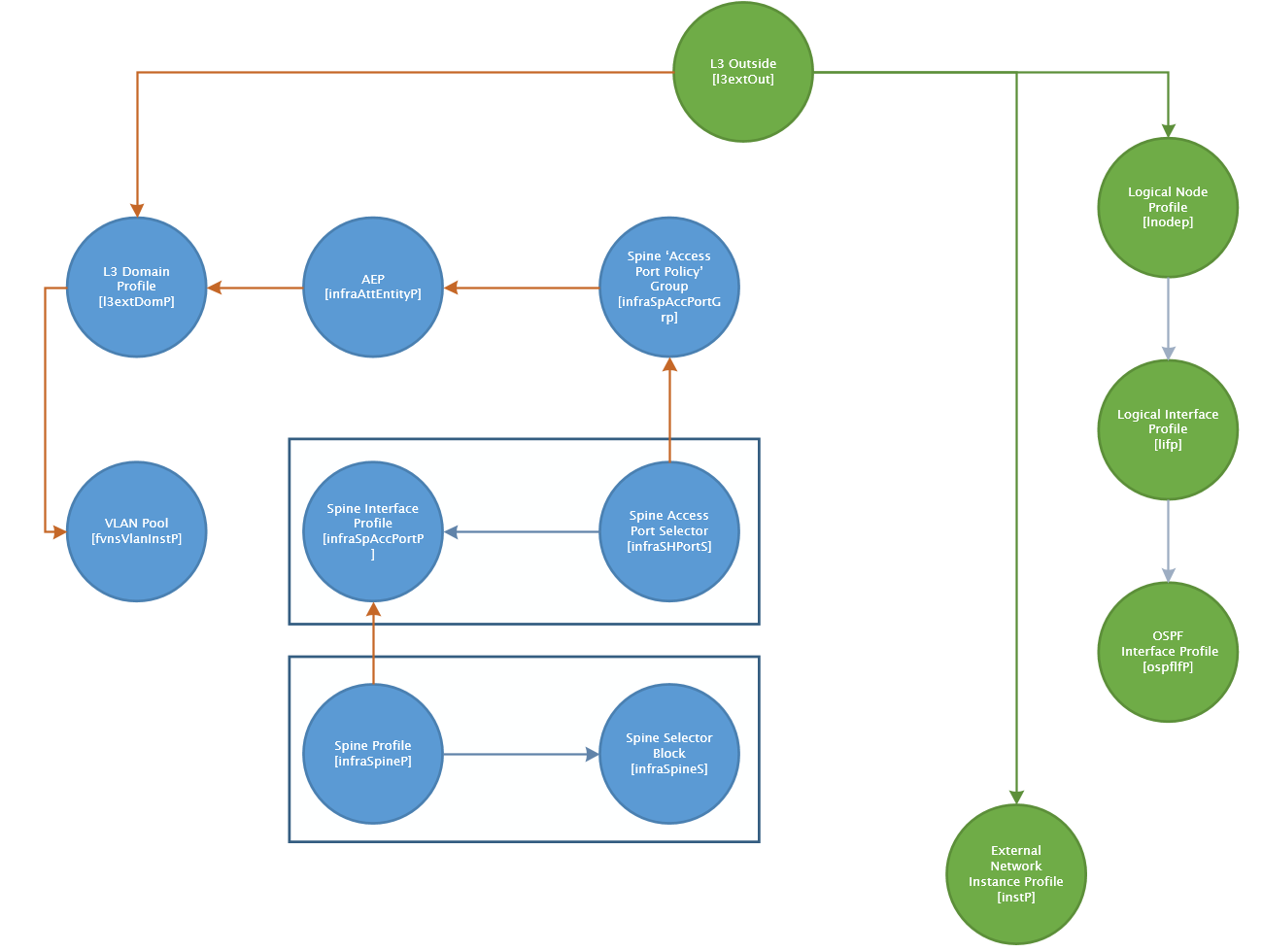
So we have briefly looked at the individual configuration areas in the GUI for multipod, this gives an understanding of what the underlying objects are that we need to configure using the REST API. We will be using XML rather than JSON for this I find XML is easier for me to read, if we were scripting the changes to the files I would possibly use JSON instead as I feel more comfortable working with JSON in Python. I have broken the configuration down into six steps or more accurately six XML files and we will step through each one noting what we need to modify in each. This is the full configuration you need to configure multipod, some CCO documents fall short at presuming you have configured other objects and the examples provided have relationships to these objects with no references in the text. When we talk about elements in the XML, we are actually referring to what the APIC calls managed objects (MO) once configured, to understand more about MO attributes refer to the Cisco APIC Management Information Model Reference. The following diagram shows the links between the MOs used in the multi-pod configuration. Some MO’s are not shown as there is no direct links between, for example the TEP Pool MO [fabricSetupPol].
BGP AS & Route Reflector
<polUni>
  <fabricInst>
     <bgpInstPol name="default">

	<bgpRRP>
	  <bgpRRNodePEp id="101" podId="1"/>
	  <bgpRRNodePEp id="103" podId="2"/>
	</bgpRRP>

        <bgpAsP asn="65001"/>

     </bgpInstPol>
   </fabricInst>
</polUni>
Add or remove elements <bgpRRNodePEp> for each RR to be configured and update element <bgpAsP> with the fabric wide AS number.
VLAN Pools & AEP
<polUni>
    <infraInfra>
        <fvnsVlanInstP name="4" descr="MultiPod L3Dom VLAN 4" allocMode="static">

            <fvnsEncapBlk name="4" descr="VLAN 4" allocMode="inherit" from="vlan-4" to="vlan-4" />
        </fvnsVlanInstP>

        <!-- AEP for MultiPod -->
        <infraAttEntityP name="AEP-MultiPod" descr="">
        	<!-- Relationship to the External Routed Domain for multipod, created in Step 2 (pre-provision)-->
        	<infraRsDomP tDn="uni/l3dom-multipod" />
        </infraAttEntityP>
    </infraInfra>
</polUni>
The parent element ‘fvnsVlanInstP’ contains the VLAN Pool configuration, unless you want to change the name or description, nothing needs to be changed for ‘fvnsVlanInstP’. Be aware that is any of these configurations, changing the name will mean you will have to ensure you also update the same name in relationship objects in the other configuration sets, if you don’t or miss one it will break the relationships and multi-pod just wont work.
The parent element ‘infraAttEntityP’ is the AEP configuration, again the name and the description can be modified but refer to previous warning. The child element ‘infraRsDomP’ is a relationship (denoted by Rs or Rt in the object name) object pointing to the L3 Domain object which we will create next. For the most part the APIC will allow pre-provisioning when the
referenced objects don’t already exist. The APIC GUI will display a status of “missing-target” instead of “formed” when the object referred to is missing, this is fine as we are about to create this object.
In short, we don’t need to make any changes to this XML to fit any deployment.
External L3 Domain for MultiPod
<l3extDomP name="multipod">
		<!-- VLAN Pool (only #4) -->
        <infraRsVlanNs tDn="uni/infra/vlanns-[4]-static"/>
</l3extDomP>
The element ‘l3extDomP’ is the L3 Domain MO. The only required configuration is the relationship to the VLAN Pool we created earlier, if we did not change the VLAN MO name earlier then we have no configuration to do on this object, but if we change the ‘l3extDomP’ name, remember the warnings given previously.
Spine Switch and Interface Policies
<!-- Spine Access Port Policy Group Creation Spine Interface Profile Spine Switches Profile -->
<polUni>
  <infraInfra>

  	<infraFuncP>
	  	<!-- Spine Access Port Policy Group uni/infra/funcprof/spaccportgrp-{name} -->
		<infraSpAccPortGrp name="MULTIPOD-ACCESS-POL-GRP">
		    <infraRsHIfPol tnFabricHIfPolName="default"/>
		    <infraRsCdpIfPol tnCdpIfPolName="default"/>
		    <infraRsAttEntP tDn="uni/infra/attentp-AEP-MultiPod"/>
		</infraSpAccPortGrp>
  	</infraFuncP>

	<!-- Spine Interface Profile -->
	<infraSpAccPortP name="MULTI-POD" descr="">
	    <infraSHPortS name="MULTI-POD-INTS" descr="" type="range">
	        <infraRsSpAccGrp tDn="uni/infra/funcprof/spaccportgrp-MULTIPOD-ACCESS-POL-GRP"/>
	        <!-- Switch Port e1/36 -->
	        <infraPortBlk name="block3" descr="" toPort="36" toCard="1" fromPort="36" fromCard="1"/>
	        <!-- Switch Port e1/32 -->
	        <infraPortBlk name="block2" descr="" toPort="32" toCard="1" fromPort="32" fromCard="1"/>
	    </infraSHPortS>
	</infraSpAccPortP>

	<!-- Spine Switches Profile -->
	<infraSpineP name="MULTI-POD-SPINE-PROFILE" descr="">
		<!-- Spine Switch Range 101-102 -->
	    <infraSpineS name="S101-S102" descr="" type="range">
	        <infraNodeBlk name="MULTIPOD-SPINE-SWITCH-101-102" descr="" to_="102" from_="101"/>
	    </infraSpineS>
	    <!-- Spine Switch Range 103-104 -->
	    <infraSpineS name="S103-S104" descr="" type="range">
	        <infraNodeBlk name="MULTIPOD-SPINE-SWITCH-103-104" descr="" to_="104" from_="103"/>
	    </infraSpineS>

	    <infraRsSpAccPortP tDn="uni/infra/spaccportprof-MULTI-POD"/>

	</infraSpineP>

  </infraInfra>
</polUni>
This XML is a little bigger and contains a few items we need to modify. The first parent element ‘infraFuncP’ does not require changes, this is the Spine Access Port Policy Group and has a reference to the name of the AEP created earlier. The other relationships ‘infraRsHIfPol’ and ‘infraRsCdpIfPol’ reference Link Layer Policies and CDP policies respectively. We have not selected any on this policy are the defaults are fine for this deployment.
The element ‘infraSpAccPortP’ is the profile in which we configure the spine ports (interfaces) we want to use on each switch that we select in the next XML element ‘infraSpineP’. The child element ‘infraRsSpAccGrp’ references the Spine Access Policy Group (‘infraFuncP’) we created in the first section of this XML. We can specify contiguous ranges of interfaces (e.g. 1/1-1/10) in a single element called ‘infraPortBlk’, if we want to specify interfaces which are non contiguous then we must create a ‘infraPortBlk’ for each interface (or ranges of contiguous interfaces). In this deployment we are using interfaces 1/32 and 1/36 so we have created two ‘infraPortBlk’s elements, one for each interface, add more lines if you want to add more interfaces per spine switch. The name of each ‘infraPortBlk’ needs to be unique within the parent element ‘infraSHPortS’ only and not system wide. For interface 1/32, we configure the attributes ‘fromCard’ and ‘toCard’ with ‘1’ and the attributes ‘fromPort’ and ‘toPort’ with ’32’.
The final element ‘infraSpineP’ defines the spine switches that contain the ports we have just configured in the ‘infraPortBlk’s. The name for the element ‘infraSpineS’ can be changed with no impact on the rest of this configuration. Each ‘infraSpineS’ contains a contiguous range of spine switches, these are defined by the child object ‘infraNodeBlk’ which provides the same function as the interface ‘infraPortBlk’ except for spine switches. The names on these ‘infraNodeBlk’ can be changed without impact or changes elsewhere in the configuration. Defining the switch range is a matter of changing the attributes ‘from_’ and ‘to_’ spine node numbers. You will notice that we have a second ‘infraSpineS’ element with a range of 103-104, the first element had 101-102, we can combine these into one ‘infraSpineS’ as 101-104 is a contiguous range, this has been split to demonstrate how to multiple ‘infraSpineS’ objects.
MultiPod TEP Pools
<!-- Create MultiPod TEP Pools Note: Only one pod/pool should be done
    at a time as Cisco recommends that once a pool is configured for a
    POD, that no other PODs/Pools should be configured until the newest
    addition has been discovered by the fabric/apic.
-->
<polUni>
	<ctrlrInst>
		<fabricSetupPol>
			<fabricSetupP podId="2" tepPool="10.2.0.0/16"/>
		</fabricSetupPol>
	</ctrlrInst>
</polUni>
During the fabric CLI setup a TEP IP Pool was created for POD1. This TEP (tunnel endpoint pool) provides IP addressing to spine and leaf switches or any device that provides a VXLAN TEP function. We need to define a new TEP IP Pool for POD2, this configuration provides just that. Define the new POD number in the ‘podId’ field and in the ‘tepPool’ field provide the IP TEP Pool aggregate. This must be a range that is not in use anywhere else in the network and has the same rules as the POD1 TEP Pool created in the fabric setup. Be sure to create a large enough pool as this cannot be changed later (without a clean install). Cisco recommend /12 but minimum /16.
Configure MultiSite Profile (MultiPod Profile)
<polUni>
	<!-- Always configured in the infrastructure tenant tn-infra -->
	<fvTenant dn="uni/tn-infra">
		<!-- Create Intrasite/Intersite (MultiPod) Profile -->
		<fvFabricExtConnP descr="" id="1" name="Fabric_Ext_Conn_Pol1" rt="extended:as2-nn4:5:16" status=''>

		  <!-- POD 1 TEP Address - Just like the Switches, a POD has an TEP address too -->
		  <fvPodConnP descr="" id="1" name="">
		     <fvIp addr="10.96.1.96/32"/>
		  </fvPodConnP>

		  <!-- POD 2 TEP Address - Just like the Switches, a POD has an TEP address too -->
		  <fvPodConnP descr="" id="2" name="">
		     <fvIp addr="10.96.2.96/32"/>
		  </fvPodConnP>

		  <fvPeeringP descr="" name="" type="automatic_with_full_mesh"/>

		  <l3extFabricExtRoutingP descr="" name="ext_routing_prof_1">
		  	 <!-- Defines the IPN networks - aggregates allowed, multiple l3extSubnet can be defined if reqd. -->
		     <l3extSubnet descr="" ip="10.96.0.0/16" name=""/>
		  </l3extFabricExtRoutingP>

		</fvFabricExtConnP>
	</fvTenant>
</polUni>
This configuration set provides the MultiPod setup. The elements ‘fvPodConnP’ are defined per POD, these define a POD TEP address, just like switches have TEP addresses, a POD has a TEP address of its own. The TEP addresses assigned to these POD’s have been taken from the assigned IP aggregate for the sites IPN addressing (see the IPN part of this blog here). Make sure the ‘id’ field matches the POD ID and the IP address is assigned as a host address (/32). The final piece of configuration we need to adjust is providing the aggregate address for the IPN networks in parent element ‘l3extFabricExtRoutingP’ and specifically in the child element ‘l3extSubnet’. We have a single aggregate that covers all the IPN networks today and for scaling beyond the maximum of the 12 Pod limitation in the future should this limitation be lifted. Where a single aggregate does not cover all the IPN addresses, add additional ‘l3extSubnet’ elements, names are not mandatory for these elements.
L3Out for MultiPod
<polUni>
	<!-- Always configured in the infrastructure tenant tn-infra -->
	<fvTenant dn="uni/tn-infra">

		<!-- OSPF Interface Policy - used Later to IPN -->
		<ospfIfPol cost="unspecified" ctrl="advert-subnet,mtu-ignore" deadIntvl="4" helloIntvl="1" name="OSPF-Interface-Policy" nwT="p2p" pfxSuppress="inherit" prio="1" rexmitIntvl="5" xmitDelay="1"/>

		<!-- L3Out for MultiPod -->
		<l3extOut descr="" enforceRtctrl="export" name="multipod">
		  <ospfExtP areaId='0' areaType='regular'/>
		  <bgpExtP />
		  <l3extRsEctx tnFvCtxName="overlay-1"/>
		  <l3extRsL3DomAtt tDn="uni/l3dom-multipod"/>

		  <l3extLNodeP name="Spine-Node-Profiles">
		  	 <!-- l3extRsNodeL3OutAtt for each Spine Node that connects to the IPN, includes all PODs -->
		  	 <!-- Configure each IP connected spine switch with a RouterID and Loopback Address -->
		  	 <!-- POD 1 Spines using Router ID as Loopback IP -->
		     <l3extRsNodeL3OutAtt rtrId="10.96.1.3" rtrIdLoopBack="yes" tDn="topology/pod-1/node-101">
		        <l3extInfraNodeP descr="" fabricExtCtrlPeering="yes" name=""/>
		     </l3extRsNodeL3OutAtt>

		     <l3extRsNodeL3OutAtt rtrId="10.96.1.4" rtrIdLoopBack="yes" tDn="topology/pod-1/node-102">
		        <l3extInfraNodeP descr="" fabricExtCtrlPeering="yes" name=""/>
		     </l3extRsNodeL3OutAtt>

		     <!-- POD 2 Spines with seperate IP to Loopback IP-->
		     <l3extRsNodeL3OutAtt rtrId="103.103.103.103" rtrIdLoopBack="no" tDn="topology/pod-2/node-103">
		        <l3extInfraNodeP descr="" fabricExtCtrlPeering="yes" name=""/>
		        <l3extLoopBackIfP addr="10.96.2.3/32" descr="" name=""/>
		     </l3extRsNodeL3OutAtt>

		     <l3extRsNodeL3OutAtt rtrId="104.104.104.104" rtrIdLoopBack="no" tDn="topology/pod-2/node-104">
		        <l3extInfraNodeP descr="" fabricExtCtrlPeering="yes" name=""/>
		        <l3extLoopBackIfP addr="10.96.2.4/32" descr="" name=""/>
		     </l3extRsNodeL3OutAtt>

			 <!-- On each spine switch defined above, configure the IPN connected interfaces on each spine sw -->
		     <l3extLIfP name='Logical-Interface-Profs'>
		     	<!-- Spine 101 Interfaces -->
		        <l3extRsPathL3OutAtt descr='IPN-POD1-01-e1/1' tDn="topology/pod-1/paths-101/pathep-[eth1/36]" encap='vlan-4' ifInstT='sub-interface' addr="10.96.1.254/30" />
		        <l3extRsPathL3OutAtt descr='IPN-POD1-02-e1/1' tDn="topology/pod-1/paths-101/pathep-[eth1/32]" encap='vlan-4' ifInstT='sub-interface' addr="10.96.1.246/30" />
		        <!-- Spine 102 Interfaces -->
		        <l3extRsPathL3OutAtt descr='IPN-POD1-01-e1/5' tDn="topology/pod-1/paths-102/pathep-[eth1/36]" encap='vlan-4' ifInstT='sub-interface' addr="10.96.1.250/30" />
		        <l3extRsPathL3OutAtt descr='IPN-POD1-02-e1/5' tDn="topology/pod-1/paths-102/pathep-[eth1/32]" encap='vlan-4' ifInstT='sub-interface' addr="10.96.1.242/30" />
		        <!-- Spine 201 Interfaces -->
		        <l3extRsPathL3OutAtt descr='IPN-POD2-01-e1/1' tDn="topology/pod-2/paths-103/pathep-[eth1/36]" encap='vlan-4' ifInstT='sub-interface' addr="10.96.2.254/30" />
		        <l3extRsPathL3OutAtt descr='IPN-POD2-02-e1/1' tDn="topology/pod-2/paths-103/pathep-[eth1/32]" encap='vlan-4' ifInstT='sub-interface' addr="10.96.2.242/30" />
		        <!-- Spine 101 Interfaces -->
		        <l3extRsPathL3OutAtt descr='IPN-POD2-01-e1/5' tDn="topology/pod-2/paths-104/pathep-[eth1/36]" encap='vlan-4' ifInstT='sub-interface' addr="10.96.2.250/30" />
		        <l3extRsPathL3OutAtt descr='IPN-POD2-02-e1/5' tDn="topology/pod-2/paths-104/pathep-[eth1/32]" encap='vlan-4' ifInstT='sub-interface' addr="10.96.2.246/30" />

				<!-- OSPF Interface Profile - Authentication -->
		       <ospfIfP>
		       	   <!-- OSPF Interface Policy Name (timers etc)-->
		           <ospfRsIfPol tnOspfIfPolName="OSPF-Interface-Policy"/>
		       </ospfIfP>

		     </l3extLIfP>
		  </l3extLNodeP>

		  <!-- External Network Instance Profile -->
		  <l3extInstP descr="multipod external network instance profile" name="Ext-Net-Instance-Prof">
		      <fvRsCustQosPol tnQosCustomPolName=""/>
		  </l3extInstP>
		</l3extOut>
	</fvTenant>
</polUni>
This is the configuration for the L3Out, the Layer 3 connection to the IPN network. This defines the spine interface IP addresses, loopback addresses policies for OSPF.
We first define a policy for OSPF ‘ospfIfPol’, the timers can be adjusted to your requirements, the policy is set to point to point which matches the IPN device configurations, the attribute/value [ctrl=”advert-subnet,mtu-ignore”] must have the mtu-ignore but can optionally advertise the p2p subnet
The element ‘l3extLNodeP’ contains the child elements ‘l3extRsNodeL3OutAtt’ representing each spine switch connecting to the IPN, each of these elements contain the spine switch router ID and loopback IP address configuration. We can provide a router id (rtrId) and have this also be the loopback address if we set the field ‘rtrIdLoopback’ to ‘yes’ in the spine switch element ‘l3extRsNodeL3OutAtt’ We need to ensure that the ‘tDn’ field has the correct path to the spine switch we are assigning the configuration to. Ensure the pod-{id} and node-{id} are correct. Pod 1 has the router id as the loopback address, for Pod 2 we have provided a router id for both spine switches but do not want to use this as a loopback address, so we set the ‘l3extRsNodeL3OutAtt’ field ‘rtrIdLoopBack’ to ‘no’ and add a child element ‘l3extLoopBackIfP’ with the field ‘addr’ set to the IP address we want to use as a loopback IP address. We could also add another ‘l3extLoopBackIfP’ child element but instead of an IPv4 address we could add an IPv6 address too. If you set the ‘rtrIdLoopback’ to no, you must define ALL the loopback addresses in ‘l3extLoopBackIfP’ child elements, if you set ‘rtrIdLoopback’ to yes, any ‘l3extLoopBackIfP’ child elements will be ignored and only the router id will be used.
We now have the spine switches configured but we also need to configure the spine switch interfaces. The parent element ‘l3extLIfP’ contains an ‘l3extRsPathL3OutAtt’ element for every interface connecting to the IPN network, in this design we have two interfaces per spine switch connecting to the IPN. In each of the interfaces defined, the ‘descr’ field states the spine switch name with the interface id, the ‘tDn’ field must contain the correct path with the correct pod id, the paths-{id} is the spine id number, the pathep-[{int}} is the interface id which is one of the ones defined in the earlier section for Interface Selector Profiles. the ‘encap’ field must be ‘vlan-4’, the ‘ifInst’ is set to ‘sub-interface’ to give us the flexibility to use this interface for other L3 connections should we require this and the ‘addr’ field is the interface IP address which must be in the same subnet as the connected IPN device. Add or remove these lines to match your design.
The rest of the configuration does not require any changes and references the OSPF policy we created in the first part of this configuration set.
Fabric Discovery & Validation
The third part of this blog will go through fabric discovery of the additional pod and validation on the APIC. Part one of this series focused on configuration and validation of the IPN .
Hi Simon
I am almost sure it went up only when I added a policy group under “Fabric->Fabric Policies->Pods->Policy Groups” and chose the default BGP RR policy, but now reading your post I think the result would have been the same had I just enabled the BGP RR under the System as you suggest.