Orchestrator of Orchestrators
Intention
I set myself a challenge a while ago to write a workflow engine which would take a declarative input which would in turn instruct the workflow engine to perform a set of tasks with the output being the intended resource. Whilst this initial challenge was interesting, it grew to a full system very quickly through the learning process in regards to system architecture and flexibility.
I am a networker by ‘trade’ and have been for over 20 years but before that I started out coding and have been coding in the background ever since. The last decade has seen a proliferation of good solid APIs provided by end systems such as VMWare’s vCenter, Cisco’s ACI, Red Hat Satellite (Foreman, Pulp, etc) and so on. Working with these systems over the years has always intrigued me in actually developing code to fully integrate these systems to build resources end to end. No different that the public cloud providers (AWS, Azure, GCP, etc) and again no different that other on premise off the shelf solutions like Cisco’s Nexus Dashboard.
How hard can this be ? Well its hard, at least until the architectural principles are understood in terms of what the system should and should not do, and also where the boundaries are. Added into this is also how flexible can the system be to allow additional (known and unknown) features / functionality in the future. The process of getting to the point of the system I am going to talk about has taken time, many iterations and mostly in my own time so progress was slow but a hell of a lot of fun doing it and the insight and knowledge gained I feel is invaluable.
The big problem is, it never ends and my feature list grows all the time, which is why this is a personal project and something one person cannot physically accomplish on their own.
60,000 ft. Thinking
We have excellent off the shelf orchestration tools, we focus on the most popular two out there today Ansible and Terraform. as we know both of these have wrappers in the form of Ansible Tower/AWX and TFE which provide UI’s but most importantly solid understandable REST API’s. I have worked with both of these tools and really like what they do and how they do it. In other words they are fit for purpose and fill the needs very well in terms of infrastructure provisioning and configuration management.
Using these tools requires the use of the UI of which are both functional but do require the end user to have some reasonable technical knowledge. if we use the REST API to instruct these tools to do our bidding, well then we need some code to interface to the REST API. There are situations that require both of these tools. For example, we may want Terraform to provision the infrastructure (Network, vFirewall, Virtual Machines, etc) and have Ansible manage the configuration. In addition these resources will need to be added to management and monitoring systems via Ansible or directly. So now we have a situation where we have to use the UI (or CLI) on Terraform then after successful provisioning we then need to use the UI/CLI for Ansible to perform the configuration tasks. But hold on, we also need some other data up front. We need to know what networks to use, what IP addresses, gateways, VM images, disk configurations, etc. The list is long.
So what if we design a system to allow a non-technical user or a technical user with options to customise the resources. We can provide a non-technical user a list of standard resources with all the tech stuff already known. In the case of a non-technical user, we are referring to a user that does not have intimate knowledge of the infrastructure end to end. So this may be a web developer who’s job it is to (well..) develop web based Intranet applications. This user just wants a VM to develop the application without having to wait days for the entire IT team to figure out where it should go, what IP addresses, what security to apply to it. Also we can add a third user type, not so much a user but an end system. Lets take an example of horizontally scaling a system. Where a systems resources are hitting the preferred limits, a monitoring system could call the API of this system to ask for a few new servers to be added to the system.
Use Case (Simple)
Lets say a web developer wants a new Red Hat server VM, they know they want the VM to be on a network called ‘INTRANET_DEV’, with 2 CPU, 8GB Memory and 100GB of storage, that is all they care about. Just give me that VM, tell me when its ready and quickly please.
Simple and obvious use case, but consider that a VM could be a Virtual Appliance, it could be a 20 VM’s that we need for only a short period of time or even long term VM’s. The list could grow very easily if we think a little.
Architectural Approach
We need a few ‘systems’ to manage this process if we are to be able to scale and add to the system without breaking it every time we add new features. we don’t want masses of intricate code to decipher where we have to pull it apart when we want to add Windows servers, Virtual Appliances or new features.
These ‘systems’ are best built as microservices, each performing a bounded set of tasks with a defined input and output. With each system built around a concept of a REST API interface as a service and a core service which performs the tasks we have a defined input and output via the REST API and a core service that focuses on pending tasks/requests provided by the input via the REST API.
Systems
What systems do we need. Well I started off talking about a workflow engine, this was my starting point until the entire thing grew on me. Most of these services are implemented as two separate components, one being the REST API running in its own process (NGINX) and the second being a separate python process being the service. These don’t directly communicate (at least at the moment). The API will add or update entries in the microservices dedicated database and the service will poll the database for records that need to be processed.
I had initially used Redis as a messaging platform between the microservices but came up against some limitations which started to make things very complex so moved to using REST API’s as the interface to any microservice. Having said that, as I stated above the two components of a microservice (API & Service) effectively communicate via database records. Whilst this works ok and doesn’t stress the system, I am inclined to look as using Redis or RabbitMQ for communication between components within the microservice.
Workflow Engine (Microservice)
The workflow engine’s task is to take in a declarative input in JSON format via the workflow engine API known as a ‘workflow request’. This input declares a template to use and a bunch of configuration data. The template defines what tasks to perform. A task is a python module that performs a single ‘task’ and reports back to the workflow engine the status of the task. The workflow engine uses the requested template to create a DAG (Directed Acyclic Graph) to ensure tasks are performed in the correct order and to understand when failure of a task should result in the failure of the entire workflow request or not.
I will go into detail around the workflow engine and other microservices in separate posts but to visualise the workflow engine at a high level, it looks like this.
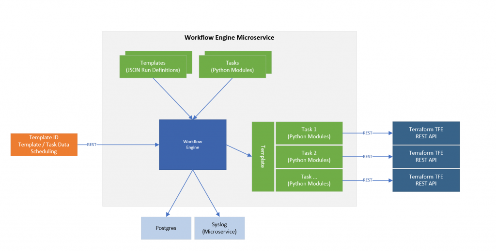
On the left we have the input to the workflow engine as discussed being a declarative set of data including a template that should be used with this data. At the top of the diagram we have two other inputs but more static and not part of the workflow request. The tasks are Python modules that perform a single task. If we use Terraform as an example, using the TFE REST API we need to use 5 different REST API calls to have a TFE workspace run and apply start. So each task wraps a single REST API call. This was when a REST API call to TFE completes the data ad status is passed back to the workflow engine which then runs the next task in the DAG. This ordered orchestration is the result of the template (top left in the diagram). The template defined the order and required input data to complete all tasks in the template.
Using templates which are again a declarative structure (JSON) means we can create new ones and drop them into the system without modifying any code. The reason the tasks only implement one single job/task, in this case a single REST API call, is so we can reuse the tasks in the templates in different orders or different combinations. So once we build up a a catalog of tasks, it becomes easy to just create another template. The tasks are Python code which are subclassed to ensure that there are required methods available for the engine to interact with them.
To the right of the diagram, the example shows the engine interacting with the template and the tasks defined in the template where each task is calling a single TFE REST API.
In addition the Workflow Engine has a database on Postgres and uses a Syslog microservice to log system and workflow events. Each workflow request and the associated tasks that are run all log to individual log files which are uploaded to the log data store after the workflow request has completed. Redis is also used by the engines tasks to store persistent data. The subclasses of a task actually override the usual python methods of storing the data in a class dict and instead intercept these calls to create, set and modify variables to use Redis instead to store the data. This work well when the system is stopped during a task and the task is automatically restarted. This way the data in the variables is the same as the task last had when it was incorrectly terminated. This permits re-runs, no erroneous creation of new data and orphaning task data. I will explain this more in the post specific to the Workflow Engine.
That is probably enough on the workflow engine for the moment, as I said we will return to this in a separate post to discuss in detail how this is implemented. For now lets look at the other microservices that make up this system.
A more in-depth discussion on the workflow engine can be found here.
API Gateway
The API Gateway is the primary entry point into the system, it proxies some requests to backend microservices via their API’s instead of allowing access directly to backend microservices REST API interfaces. The REST API’s provided on the gateway are used by the Web UI and any other separate system. There is authentication provided on these interfaces and authentication tokens are passed though the system so each microservice can authenticate the request. Authorization is on my list of to-do’s but something I have not got round to yet.
The gateway also connects directly to some end systems like vCenter and ACI but this access is RO and is to gather data required for the UI such as network names, vCenter resources which are presented as a matrix of options where an admin can permit or deny resources to be built on particular storage and compute cluster combinations. This also ensures that only valid combinations can be selected. The status of requests along with logs and errors can also be retrieved via the REST API.
When a request for a resource is submitted to the API Gateway, basic validation is performed (basic as most of the submitted data is validated later in the backend microservices). The request is then pushed to the ‘Requests Orchestrator’ microservice via its own REST API.
Requests Orchestrator
The Requests Orchestrator’s primary job is to take a request via the API, perform some additional validation of the submission, store the submission in a request file on disk and create a ‘Request ID’ and a ‘Trace ID’ which is embedded in the request. The trace ID is used (and required) by all microservices so it is possible to track the request(s). The reason for the two ID’s is that a single request can spawn off more requests internally with new ID’s but the trace ID will never be changed. This way all actions taken will be logged with the trace id as well. It is also possible to re-submit a request to run again after a failure state. This re-run will have a new request ID but will have the same trace id.
An email is also sent to a pre-defined email(s) for awareness that a new resource request has been received with details of the request.
At this point based on the data provided in the request, this service then resolves this to a Workflow Engine template. So in the example where the resource is for a Unmanaged Virtual Machine, a specific template exists in the Workflow Engine for this resource request. The ‘unmanaged’ part of that is a separation between using Terraform for the build or Ansible. The definition of managed in this context is that Terraform when it runs will ensure the resource(s) it runs against will always be as per the TF file for the resource and if not, TF will try to correct this by changing the resource configuration back to the TF config file state. Whereas an unmanaged build is built via Ansible which is a one-shot build and if the resource core state such as number of disks or memory is changed, this will not be changed back as the Ansible build scripts wont be rerun on the resource. A note on this, we typically have continuous Ansible playbooks running ensuring consistent configuration state such as SSH values, monitoring integration but usually these hourly/daily run playbooks do not check against things like CPU and memory.
An API call is made to the Workflow Engine with the data file name and location (HTTP URL) and the template name as discussed. The Workflow Engine then kicks off the template tasks as required. This is only the first use of the Workflow Engine as this initial step is to call the API’s of the ‘Resource File Management’, TFE Wrapper and Ansible Wrapper microservice which will in turn call the Workflow Engine again in order for other templates to be used to interact with TFE and Ansible.
Resource File Management
The Resource File Management (RFM) microservice is called via a workflow engine task. The task submits details of the request in terms of the ID’s and the HTTP URL of the requests file on disk (but access via HTTP URL so these service can exists on separate servers or containers). The file will be downloaded and additional validation will occur on the data file.
The RFM service will use the data in the request to determine a handler to use. A handler is a drop in Python module that understands a particular resource type like a Virtual Machine. The request can contain multiple resource type requests and therefore the RFM service will call on each handler to process the request. For example for a Virtual Machine, the Virtual Machine handler will be called and it will create additional meta data, it will also validate the data such as the number and sizes of disks against the permitted values. The final output of the handler(s) is a declarative data set that is a common format within the system, in other words a known structure to be used by other microservices.
Based on a number of factors the final output will be stored as a file within a specific git repository, this allows version tracking, rollback and ease of editing the file data if required. Each commit represents a single request and the commit ID’s are saved in the RFM database and passed back to the workflow engine when it polls the RFM service to get the request state. The repository has additional files of which one file is a metadata file which provides the detail on the resource type (‘virtual_machine’), OS type (‘centos’) amongst other things which are used in the Wrapper services.
The state of the request is now that the request data is formatted in the ‘common’ format with a git commit ID (known file state at a point in time), git URL and accessible via SSH from other microservices.
As we use git commits, a microservice can use these to ensure the system only runs on specific files and file versions.
Ansible Wrapper
There are two core wrapper services, one for Terraform (TFE) and the other for Ansible (Tower/AWX). We will continue with the example of an unmanaged virtual machine so the TFE wrapper service will not be called by the workflow engine and only the Ansible Wrapper service.
As discussed in the previous section, the data required by the Ansible Wrapper microservice is the requested resources Git URL and Git commit hash. Other data like the user tokens are also passed of course.
The job of the Ansible Wrapper microservice is to receive the above data as discussed via the REST API and fundamentally pull the common request file from the Git repo, parse the data. The Git repo metadata file is parsed for the Workflow Engine template to use. This permits each resource type to have its own repo with metadata providing the path to creating the resource stored alongside the resource requests.
This service will create the payload format for the Ansible Tower/AWX REST API payload (extra_vars) and embed this into the Workflow Engine request. The service will then request the Workflow Engine to run the specific template for the creation of a virtual machine with Ansible Tower/AWX with this data. Note, at this stage we are already in a workflow and are requesting another workflow to be created inside the outer workflow. This is why we have the trace ID’s so we can track the creation end to end.
Terraform Wrapper
The Terraform (TFE) wrapper performs the same task as the Ansible Wrapper except the output to the Workflow Engine requests the engine to run a template used for calling Terraform tasks and formats the data in the Terraform tf file format.
These wrapper services take the common format and parse and format the data to the end orchestration systems native format.
File Store
We spoke about storing the initial request file on disk. Well we are actually using a dedicated microservice for this purpose called ‘File Store’. The file store is a HTTP server that allows uploads of files and also the download of files. The ‘Resource File Management’ API uploads these files to the file store via the file store REST API. Any other service that wants access to the raw request can pull this data via the HTTP URL for the file. The ‘Resource File Management’ service pulls these down using the URL to process the request.
Syslog
The Syslog microservice is just that, a custom Syslogger, honestly I want to enhance this and use it as a proxy to something more suited like Splunk or Elasticsearch, Logstash, and Kibana. But for the time being this works. I have started to integrate Promethous & Grafana for stats though only basic stats like running jobs etc. I think logging and metrics are a nice group to look at together some time.
Redis
Although not a microservice per se, it is used for a few different purposes. As discussed its used by the Workflow Engine tasks as a variable store backing but is also used by all the services and internal components as a service presence / status reporter.
For the presence side of things, when each service (or sub service component) starts, it registers itself on Redis using a custom python presence module which reports the service status and metadata about the platform it is running on, python version etc. The status is refreshed in intervals in the order of 5s so the system status can be viewed as a whole on a UI dashboard.
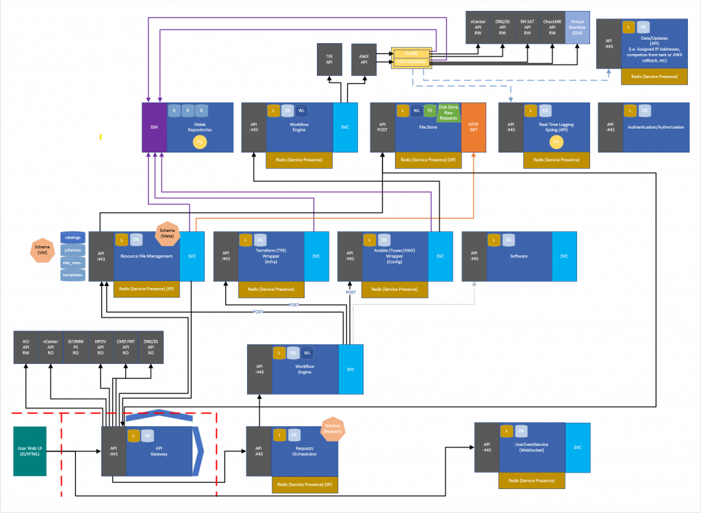
How it fits together
So that’s a lot of words, but to visualise it, this is how the various microservices fit together, starting bottom left to top right.
Next ….
Ok so more to come with individual pages per microservice and maybe a few videos of a request end to end. I am working on another iteration of the workflow engine and will make this public on a git repo near you soon.