ACI & Kubernetes – The Cisco K8s CNI (Part One)
There are a few types of solutions for using K8s with ACI certainly in terms of integration with ACI. The point of this read is to look at the Cisco CNI for K8s and hows it operates with ACI, the pros and cons and what options we have. I will be using a manual vanilla K8 deployment build on virtual machines, there is a follow up read about using K8s with ACI, Calico and MetalLB which is running on bare metal (LINK TBA).
The wrap up and comments are in Part Two if you want to skip over to that!
I have 5 CentOS 7 virtual machines (1x Master, 4x Worker) running on VMware (ESXi & vCenter) using the ACI VMM Domain integration for VMWare. I won’t be going through the setup step by step in detail but I will outline the build steps.
The Cisco K8 CNI is used for other types of integrations as well, including Red Hat OCP and Rancher integration with ACI. As an aside the Rancher integration also includes a dedicated VMM Domain in ACI.
Unsure of what a CNI is for ? take a look at this video: An Introduction to CNI – KubeAcademy
Design
Firstly we need to cover a few things off like VLAN ID’s & IP addressing for the various networks we need. We have the following;
| Network | Description/Notes | VLAN ID | IP Network |
| Node Subnet | ACI BD & kubeinit pod-network-cidr, Use to SSH/Manage host via standard EPG. | 3900 | 172.20.0.1/16 |
| Pod Subnet | ACI MUST use first in range. Each deployed Pod gets a unique IP from this range. | – | 172.21.0.1/16 |
| K8 Service CIDR | K8 Service ‘Cluster-IP’ assignments. e.g. – kubectl get service -A {CLUSTER-IP} | – | 172.22.0.0/16 |
| Node Service Subnet | ACI Service Graph PBR Subnet. Used in ACI SG PBR redirect policy, IP per K8 node. | 3950 | 172.25.2.1/24 |
| External Service Subnet (Dynamic) | CNI Assigned Service Load Balancer IPs. e.g. kubectl get service -A {EXTERNAL-IP} | – | 172.25.0.1/24 |
| External Service Subnets (Static) | Statically Assigned Service Load Balancer IPs | – | 172.25.1.1/24 |
| ACI Infra VLAN | ACI Infra VLAN ID | 3967 | Infra/DHCP |
| Opflex VMM Multicast | Unique Opflex VMM Multicast Range | – | 225.20.1.0/16 |
As per the above table, we need to assign networks as shown in the ‘IP Network’ column and also VLAN ID’s for the ‘Node Subnet’ and ‘Node Service Subnet’. The ACI Infra VLAN ID is the one configured during the fabric setup.
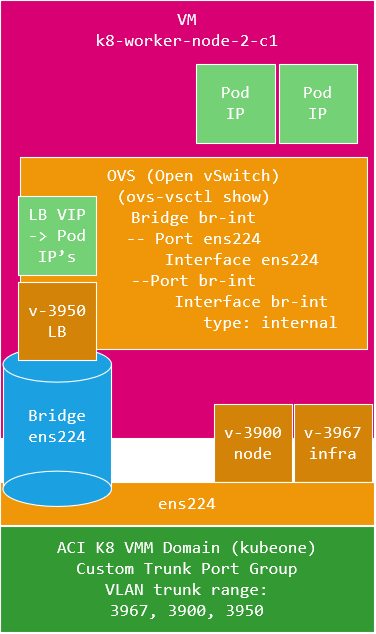
As we can see we have three VLAN’s, in this build I have each K8 virtual machine with a single interface (vNIC) connected, therefore we need a VMWare Trunk Port Group created to trunk all these three VLAN’s to the K8 node, this is actually created by the provisioning tool for you. The K8 node interface will be created as two (yes two) sub-interfaces for VLANs 3900 and 3967 with IP address assignments on VLAN 3900, but 3967 (infra VLAN) will be DHCP and obtain an IP address from the APIC as would a normal ACI switch.
VLAN 3950 is not configured as an interface on the K8 host, this is automatically configured by the ACI CNI internally within K8’s. The ACI CNI uses OVS as its switch internally and this OVS instance is configured to bridge the interface from the host to the CNI OVS instance, so VLAN’s 3900 and 3967 are terminated on the host, but all other VLAN’s (3950) then bridge into the CNI OVS instance.
An important point to note is that as we are connecting to the ACI infra VLAN, we must select the ‘Enable Infra VLAN’ option in the AEP connected to the VMM DVS domain to permit the VLAN use on the DVS.
So we have something that looks like this per K8 node.
In addition each network given in the above table is given as a host address (with the exception of the multicast range) in a network, these host addresses are configured in the ACI CNI setup configuration file for use by the ACI CNI. If we compare to the command we use for kubeadm init, we can see the correlations.
kubeadm init --pod-network-cidr=172.21.0.0/16 --service-cidr=172.22.0.0/16We see that the ‘pod-network-cidr’ network is the Pod Subnet in the above table and the ‘service-cidr’ is ‘K8 Service CIDR’.
Setup
Now we have these details together, we can create the configuration file used for ACI CNI provisioning. The ACI CNI provisioning tool is a Python based tool and can be installed with ‘pip install acc-provision’ (https://pypi.org/project/acc_provision/).
The tool will create a default configuration file for you to work with – use;
acc-provision --sample -f kubernetes-1.20 > aci-containers-config-lab.yamlTaking the settings we have defined above, we can edit the config file as shown (this is stripped down for ease of reading but fully functional).
aci_config:
  system_id: kubeone            # opflex cluster distinct ID (A Tenant will be created with this name)
  apic_hosts:                   # List of APIC hosts to connect for APIC API
  - 192.168.178.233
  vmm_domain:                   # Kubernetes container domain configuration
    encap_type: vxlan           # Encap mode: vxlan or vlan
    mcast_range:                # Every opflex VMM must use a distinct range
      start: 225.20.1.1
      end: 225.20.255.255
    nested_inside:
      type: vmware              # Specify the VMM vendor (supported: vmware)
      name: DVS_PROD_STD        # Specify the name of the VMM domain

  # The following resources must already exist on the APIC.
  # They are used, but not created, by the provisioning tool.
  aep: AEP_PROD_STD             # The AEP for ports/VPCs used by this cluster
  vrf:                          # This VRF used to create all kubernetes EPs
    name: VRF_COMMON
    tenant: common              # This can be system-id or common
  l3out:
    name: L3_INTERNET           # Used to provision external IPs
    external_networks:
    - EPG_DEFAULT               # Used for external contracts

# Networks used by ACI containers
net_config:
  node_subnet: 172.20.0.1/16       # Subnet gw to use for nodes (node vlan - kubeapi_vlan)
  pod_subnet:  172.21.0.1/16       # Subnet gw to use for Kubernetes
  extern_dynamic:  172.25.0.1/24   # Subnet to use for dynamic external IPs
  extern_static:   172.25.1.1/24   # Subnet to use for static external IPs
  node_svc_subnet: 172.25.2.1/24   # Subnet to use for aci service graph, not kubeadm init --service-cidr
  kubeapi_vlan: 3900               # The VLAN used by the physdom for nodes
  service_vlan: 3950               # The VLAN used by LoadBalancer services
  infra_vlan: 3967                 # The VLAN used by ACI infra
  interface_mtu: 8900              # min = 1280 for ipv6, max = 8900 for VXLAN (VM NIC should be this or greater)

# Configuration for container registry
registry:
  image_prefix: noiro                   # e.g: registry.example.com/noiro
  # image_pull_secret: secret_name      # (if needed)

kube_config:
  snat_operator:
    contract_scope: global
We have covered most of these settings and the reminder I hope are self explanatory, just to be clear that the ‘system_id’ will be created as a tenant on ACI, so in this build the provisioning tool will create a tenant called ‘kubeone’ which will contain most of the K8 deployment. A K8 VMM domain called ‘kubeone’ will also be created and finally I have specified a L3Out in the common tenant for external fabric access to the K8 deployment LB VIP’s. You can create the tenant before running the provisioning tool, you would do this if you want the L3Out to be used in this tenant and as you need to create the L3ut before running the tool, you would of course need to create the tenant first.
With this configuration ready, we run the provisioning tool to generate the K8 configuration file. Run this as;
acc-provision -c aci-containers-config-lab.yaml -o aci-containers-lab.yaml -f kubernetes-1.20 -a -u {ACI-ADMIN-USER} -p {ACI-USER-PASS} The input file ‘ aci-containers-config-lab.yaml ‘ is the one we created earlier and the output file ‘ aci-containers-lab.yaml ‘ will be created by the provisioning tool. We will use kubectl to apply this file to the K8 master node which will pull the ACI CNI down and install. The provisioning tool will create the ACI tenant (if not already created) and ACI K8 VMM domain as well. This is not run from any of the K8 nodes as we don’t have connectivity yet (or even built them yet), whats important is that the EPGs for management (i.e. SSH) of the nodes over VLAN 3900 will be created in ACI but you will need to apply the relevent contracts for access. The EPG is in the tenant you specified in the configuration file, we specified ‘kubeone’, so the EPG will be ‘kubeone|aci-containers-kubeone|aci-containers-nodes’, add your management contract here.
We require some K8 nodes to be ready installed with docker, K8 and correctly configured as master and workers. I wont go into too much detail here as this is well documented all around the web (see some reference at the bottom of this page) but the outline steps are (after creating the VM OS instances).
The steps below I used to create a template K8 node to then clone and configure as master or worker nodes.
1. Setup connected interface with DOT1Q for VLANs 3900, 3967

For CentOS/Red Hat VLAN Interface Setup See:
https://access.redhat.com/documentation/en-us/red_hat_enterprise_linux/7/html/networking_guide/sec-configure_802_1q_vlan_tagging_using_the_command_line

Example:
[root@k8-master-node-c1 ~]# cat /etc/sysconfig/network-scripts/ifcfg-ens224
# Main Physical Interface, see subs for config
TYPE=Ethernet
BOOTPROTO=none
ONBOOT=yes
MTU=9000
DEVICE=ens224

[root@k8-master-node-c1 ~]# cat /etc/sysconfig/network-scripts/ifcfg-ens224.3900
# Node VLAN:3900 - The VLAN used by the physical domain for Kubernetes nodes.
VLAN=yes
BOOTPROTO=none
DEFROUTE=yes
IPV4_FAILURE_FATAL=no
DEVICE=ens224.3900
ONBOOT=yes
IPADDR=172.20.0.10
PREFIX=16
GATEWAY=172.20.0.1

[root@k8-master-node-c1 ~]# cat /etc/sysconfig/network-scripts/ifcfg-ens224.3967
# ACI Infra VLAN: 3967
IPV6INIT=no
VLAN=yes
BOOTPROTO=dhcp
DEVICE=ens224.3967
ONBOOT=yes

[root@k8-master-node-c1 ~] modprobe --first-time 8021q

2. Disable firewalld as iptables is used by K8

3. Install Docker
	yum check-update
	yum install -y yum-utils device-mapper-persistent-data lvm2
	yum-config-manager --add-repo https://download.docker.com/linux/centos/docker-ce.repo
	[yum list docker-ce --showduplicates | sort]
	yum install -y docker-ce-18.06.3.ce

	mkdir -p /etc/docker
	In: /etc/docker/daemon.json
                      {
                          "exec-opts": ["native.cgroupdriver=systemd"],
                          "storage-driver": "overlay2"
                      }
	systemctl start docker
	systemctl enable docker
	systemctl status docker

	cat <<EOF > /etc/sysctl.d/k8s.conf
	net.bridge.bridge-nf-call-ip6tables = 1
	net.bridge.bridge-nf-call-iptables = 1
	EOF
	sysctl --system


4. sudo yum install -y kubelet kubeadm kubectl

5. Amend the file '/usr/lib/systemd/system/kubelet.service.d/10-kubeadm.conf' and add '--network-plugin=cni'

# FILE: '/usr/lib/systemd/system/kubelet.service.d/10-kubeadm.conf'
# Note: This dropin only works with kubeadm and kubelet v1.11+
[Service]
Environment="KUBELET_KUBECONFIG_ARGS=--bootstrap-kubeconfig=/etc/kubernetes/bootstrap-kubelet.conf --kubeconfig=/etc/kubernetes/kubelet.conf --network-plugin=cni"
Environment="KUBELET_CONFIG_ARGS=--config=/var/lib/kubelet/config.yaml"
# This is a file that "kubeadm init" and "kubeadm join" generates at runtime, populating the KUBELET_KUBEADM_ARGS variable dynamically
EnvironmentFile=-/var/lib/kubelet/kubeadm-flags.env
# This is a file that the user can use for overrides of the kubelet args as a last resort. Preferably, the user should use
# the .NodeRegistration.KubeletExtraArgs object in the configuration files instead. KUBELET_EXTRA_ARGS should be sourced from this file.
EnvironmentFile=-/etc/sysconfig/kubelet
ExecStart=
ExecStart=/usr/bin/kubelet $KUBELET_KUBECONFIG_ARGS $KUBELET_CONFIG_ARGS $KUBELET_KUBEADM_ARGS $KUBELET_EXTRA_ARGS


6. systemctl enable kubelet

7. systemctl start kubelet
I then use the following steps after cloning the above VM to create masters and workers.
1. Master/Workers IP Settings
=========================================================================
Node Name			ens224.3900
=========================================================================
k8-master-node-c1 		172.20.0.10 /16 gw 172.20.0.1
k8-worker-node-1-c1		172.20.0.11 /16 gw 172.20.0.1
k8-worker-node-2-c1		172.20.0.12 /16 gw 172.20.0.1
k8-worker-node-3-c1		172.20.0.13 /16 gw 172.20.0.1
k8-worker-node-4-c1		172.20.0.14 /16 gw 172.20.0.1

2. Change Machine ID
	rm /etc/machine-id
	systemd-machine-id-setup

3. Change hostname in /etc/hostname
	hostnamectl set-hostname k8-master-node-c1
	hostnamectl set-hostname k8-worker-node-1-c1
	hostnamectl set-hostname k8-worker-node-2-c1
	hostnamectl set-hostname k8-worker-node-3-c1
	hostnamectl set-hostname k8-worker-node-4-c1

4. Change IP address for VLAN Interface 3900
	nano /etc/sysconfig/network-scripts/ifcfg-ens224.3900

5. Change MAC address to actual MAC of interface ens224.3967
	nano /etc/dhcp/dhclient-ens224.3967.conf

6. sudo nano /etc/hosts  (master & worker) - if DNS is not correctly provisioned, else omit this.
	172.20.1.10  k8-master-node-c1.prod.labs.haystacknetworks.com master-node k8-master-node-c1
	172.20.1.11  k8-worker-node-1-c1.prod.labs.haystacknetworks.com worker-node k8-worker-node-1-c1
	172.20.1.12  k8-worker-node-2-c1.prod.labs.haystacknetworks.com worker-node k8-worker-node-2-c1
        ...

7. Configure Host FW

	a. Master Node
	===============
	sudo firewall-cmd --permanent --add-port=6443/tcp
	sudo firewall-cmd --permanent --add-port=2379-2380/tcp
	sudo firewall-cmd --permanent --add-port=10250/tcp
	sudo firewall-cmd --permanent --add-port=10251/tcp
	sudo firewall-cmd --permanent --add-port=10252/tcp
	sudo firewall-cmd --permanent --add-port=10255/tcp

	firewall-cmd --zone=public --add-port=179/tcp --permanent
	firewall-cmd --zone=public --add-port=4789/tcp --permanent

	sudo firewall-cmd --reload

	b. Worker Nodes
	================
	sudo firewall-cmd --permanent --add-port=10251/tcp
	sudo firewall-cmd --permanent --add-port=10255/tcp

	firewall-cmd --zone=public --add-port=179/tcp --permanent
	firewall-cmd --zone=public --add-port=4789/tcp --permanent

	firewall-cmd --reload

8. Stop FW
	systemctl stop firewalld
	systemctl disable firewalld


9. Enable netfilter

cat <<EOF > /etc/modules-load.d/k8s.conf
br_netfilter
EOF
modprobe br_netfilter

cat <<EOF > /etc/sysctl.d/k8s.conf
net.bridge.bridge-nf-call-ip6tables = 1
net.bridge.bridge-nf-call-iptables = 1
EOF
The following steps are specific to either a master tor worker node.
MASTER

1. kubeadm init --pod-network-cidr=172.21.0.0/16 --service-cidr=172.22.0.0/16

2. nano /usr/lib/systemd/system/kubelet.service.d/10-kubeadm.conf
	KUBELET_DNS_ARGS service-cidr:172.22.0.10

3. systemctl restart kubelet

4. export KUBECONFIG=/etc/kubernetes/admin.conf
	add to nano ~/.bash_profile (if preferred)

5. Apply POD ACI Network (aci-containers-lab.yaml file is from acc-provision step)
	- kubectl apply -f aci-containers-lab.yaml

WORKERS

1. Join Workers (from kubeadm init ...)

	kubeadm join 172.20.0.10:6443 --token ... --discovery-token-ca-cert-hash sha256:....


2. update /etc/systemd/system/kubelet.service.d/10-kubeadm.conf
	KUBELET_DNS_ARGS service-cidr:172.22.0.10

3. systemctl restart kubelet
Deployment
Ok, so before we look at what this integration is all about we need a deployment on K8 to work with.
I have a container that produces and consumes multicast frames on a specific address. Each container will record the sources of the multicast packets (also packed in the payload) and create a html page listing itself and the multicast sources it has seen with a little metadata. Basically all deployed containers in pods sending multicast hellos to each other. Each container runs NGINX on port 80 which returns the html page as mentioned. I use this to also prove that this solution provides the ability to have multicast run between pods (some CNI’s don’t !!)
You can use this app if you want or your own. To deploy this one with a configured service so we have a LoadBalancer VIP assigned use the following configuration.
kind: Namespace
apiVersion: v1
metadata:
  name: multicast

---

kind: Deployment
apiVersion: apps/v1
metadata:
  labels:
    app: mcast-app
  name: mcast
  namespace: multicast
  annotations:
    opflex.cisco.com/endpoint-group: '{ "tenant":"kubeone", "app-profile":"AP_K8_EX", "name":"EPG_MCAST_EX"  }'


spec:
  replicas: 3
  selector:
    matchLabels:
      app: mcast-app

  template:
    metadata:
      labels:
        app: mcast-app

    spec:

      containers:
        - name: mcast
          image: simonbirtles/basic
          imagePullPolicy: IfNotPresent
          ports:
            - containerPort: 80
              protocol: TCP

      restartPolicy: Always
and apply it with;
kubectl apply -f ./file-name.yamlNote in the configuration file the line;
opflex.cisco.com/endpoint-group: '{ "tenant":"kubeone", "app-profile":"AP_K8_EX", "name":"EPG_MCAST_EX" }'This instructs the CNI to use the existing given Application Profile and EPG in the given Tenant, this EPG will of course contain endpoints, but what endpoints ? Well it will contain the deployment (mcast) Pod IP addresses (the ‘ Pod Subnet’ – 172.21.0.0/16 from the table in the design section). If we omitted this line, the endpoints would be in a default EPG in the kubeone tenant. By specifying a specific dedicated EPG it gives us the opportunity to apply contracts to the pods. (More on this later when we discuss the different methods of accessing the application).

We can see the ACI VMM K8 domain has been created for ‘kubeone’ in the ‘Virtual Networking’ section of the APIC.
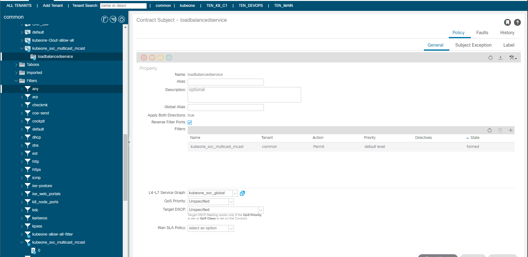
And finally lets confirm that the L3Out we specified for the LoadBalancer provided by the Cisco CNI for K8 has had an EEPG, contract and PBR service graph created.
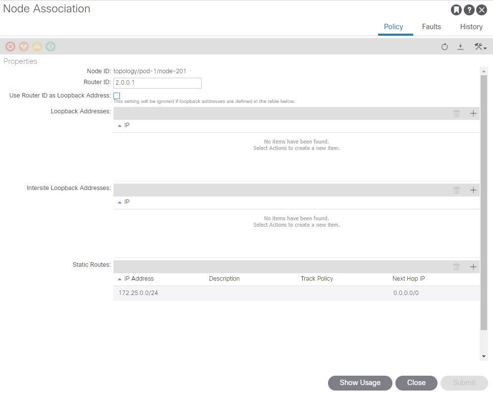
There is one vital piece of configuration we need to do on the APIC in the L3Out, which is to add a static route for the ‘External Service Subnet (Dynamic)’ into the nodes in the L3Out. (172.25.0.0/24), Recall this subnet is used for the CNI Assigned Service Load Balancer IP’s .Without this there would be no route for the LB network, we set the next hop to 0/0 which will translate to null0 in the route table.
Lets clarify this a little more in the next section.
Verifying CNI Created L3Out Application Access
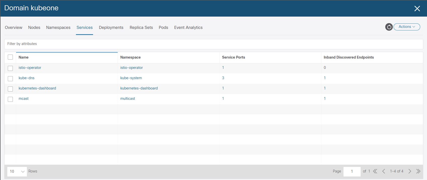
If we look at the mcast application service on a K8 node, we find the service has ‘LoadBalancer’ as a type and an ‘EXTERNAL-IP’ as 172.25.0.3, which is the LB VIP (so to speak). This VIP is the IP that the clients will use to connect to the mcast application.
The VIP is not a real address of course, and ACI uses a service graph PBR to load balance requests to that IP to the K8 nodes that are running pods for this application.
[root@k8-master-node-c1 mcast]# kubectl get services -A
NAMESPACE              NAME                        TYPE           CLUSTER-IP       EXTERNAL-IP   PORT(S)                  AGE
default                kubernetes                  ClusterIP      172.22.0.1       <none>        443/TCP                  218d
istio-operator         istio-operator              ClusterIP      172.22.242.187   <none>        8383/TCP                 218d
kube-system            kube-dns                    ClusterIP      172.22.0.10      <none>        53/UDP,53/TCP,9153/TCP   218d
kubernetes-dashboard   dashboard-metrics-scraper   ClusterIP      172.22.77.15     <none>        8000/TCP                 217d
kubernetes-dashboard   kubernetes-dashboard        ClusterIP      172.22.19.126    <none>        443/TCP                  217d
multicast              mcast                       LoadBalancer   172.22.97.1      172.25.0.3    5621:31612/TCP           5h31m
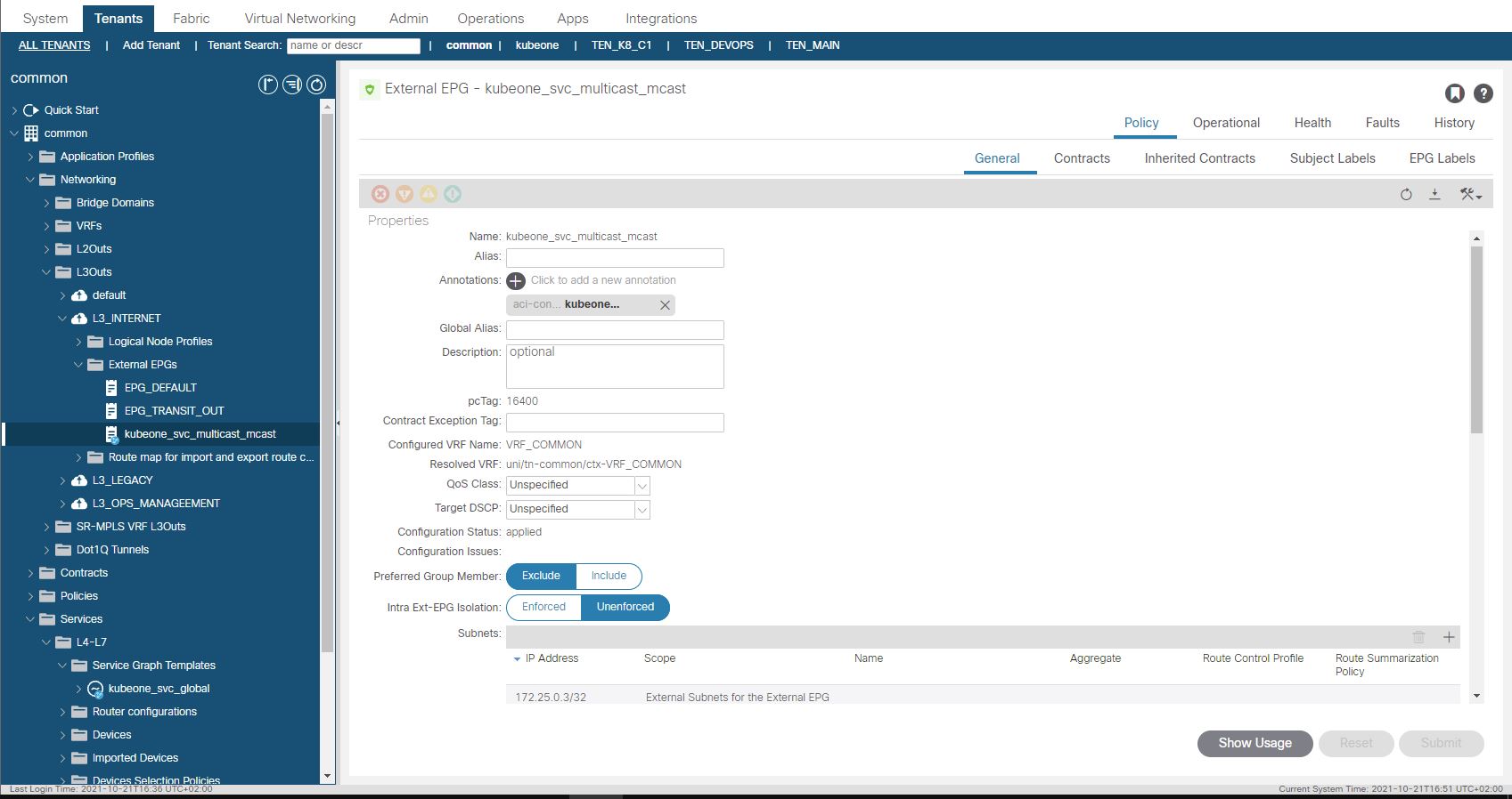
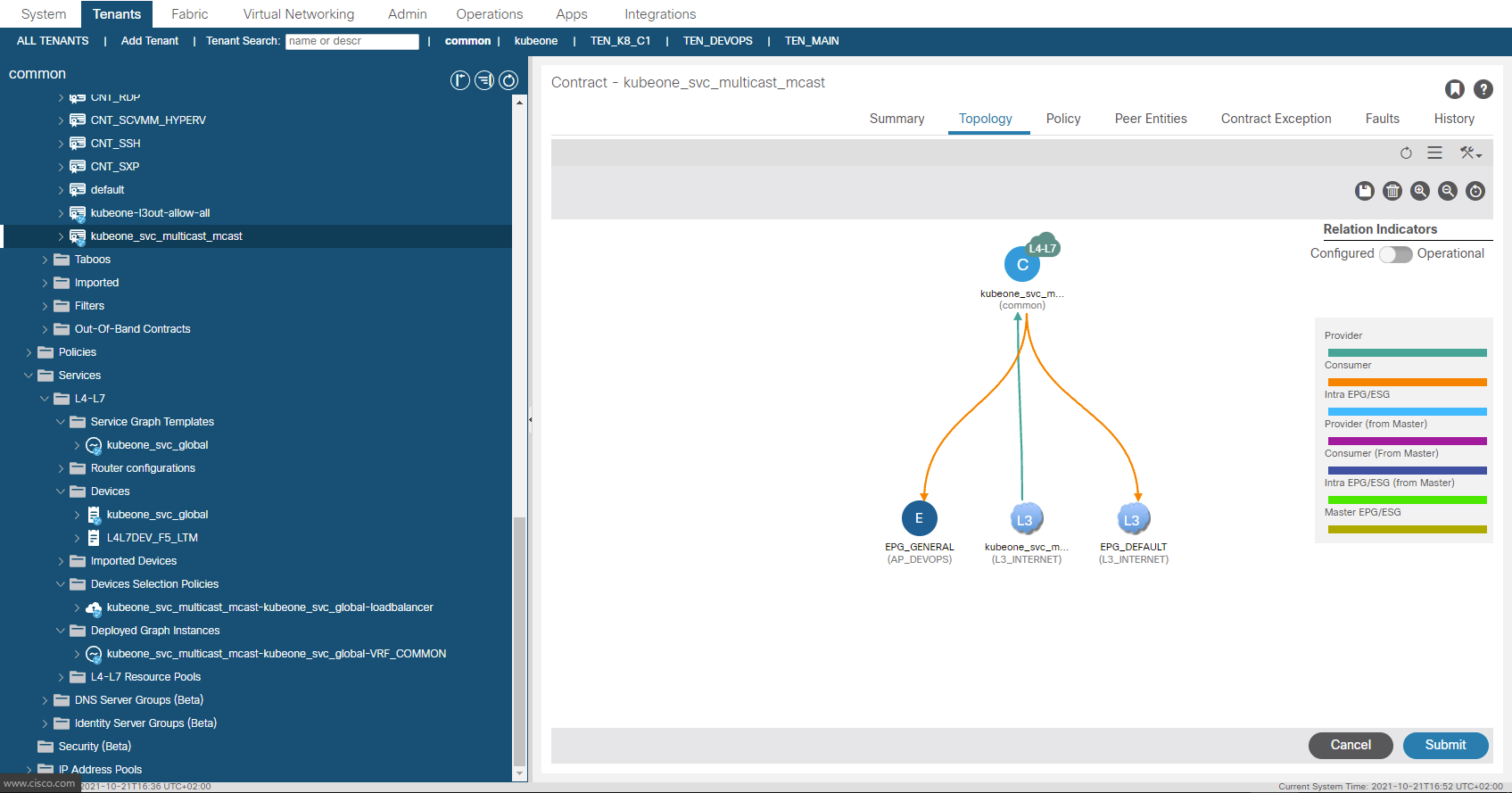
ACI creates a subnet entry in the EEPG created in the L3Out we provided. This subnet entry is 172.15.0.3/32 and is marked as a subnet external to the EPG which means the L3Out EEPG is suggesting that the IP address lives outside of the fabric via the L3Out. This is not true as you may have guessed, this is done to have traffic steered towards the EEPG as the EEPG is a provider of a contract which has a PBR service graph assigned. When the EEPG and contracts were created, the contract was also applied to the L3Out EEPG we specified in the configuration as a consumer. This means we have the ‘real’ EEPG consuming the contract being provided by the EEPG created for the CNI deployment. (Think a sort of Transit Routing)…
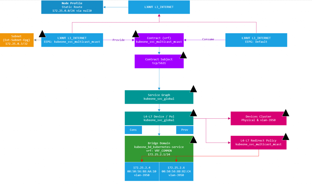
Using a diagram to make this a bit easier to visualize, we have the L3Out at the top, with two EEPG’s. The EEPG on the right (EEPG Default) is the EEPG that has external subnets defined for subnets accessible outside of the ACI fabric (the normal situation). The EEPG on the left (EEPG: kubeone_svc_multicast_mcast) has been created by the CNI, and has the LB VIP we discussed assigned to it as an external subnet (i.e. network outside the fabric). In this case the subnet (or VIP) is inside the CNI on the K8 nodes. So as we have defined a static route to null0 for the entire subnet, traffic will have a route (albeit to null0) to the subnet.
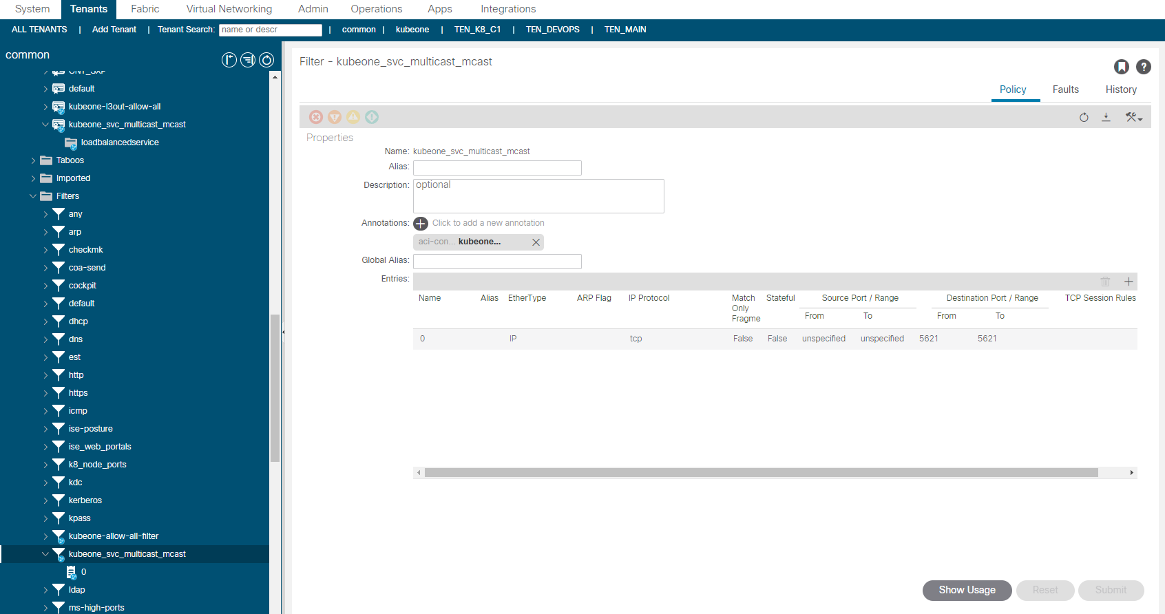
Now as the EEPG Default consumes the contract for the LB VIP port 5621 (see kubectl output above), which is mapped to port 80 for the mcast application, any traffic that enters the EEPG Default destined for 172.25.0.3 can be routed (per static) and have the contract applied due to port 5621 being specified in the contract subject and the contract subject referencing a PBR service graph.
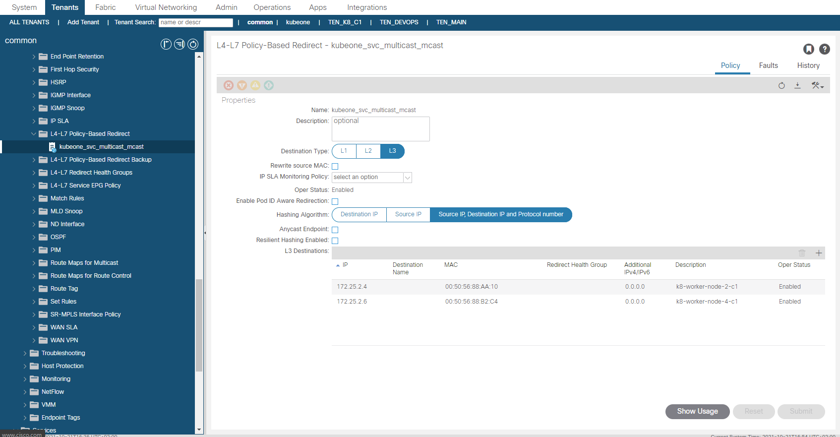
So what we have currently is traffic sourced from outside the fabric destined for the VIP of 172.25.0.3 and TCP/5621, will be processed via the consumed contract in the EEPG default. This contract redirects the traffic before getting to the provider side into the service graph. The service graph further uses a redirect policy (again all created by the CNI) to forward the traffic (at L2 – only macs change ,no L3 changes) to one of the K8 nodes running the mcast app pods.

The PBR redirect policy is shown above. The L3 Destinations are updated automatically by the CNI, so if another K8 node started to run a mcast app pod, the node would be added automatically (or removed if the opposite were true). You will notice that the MAC addresses are specified, this is important as this a L2 forwarding, in ACI v5.1+, the macs will be automatically resolved if you were doing this manually btw.
The traffic then goes to the CNI VLAN 3950 interface on the K8 node and is then routed to a pod by the CNI as shown in the diagram below.
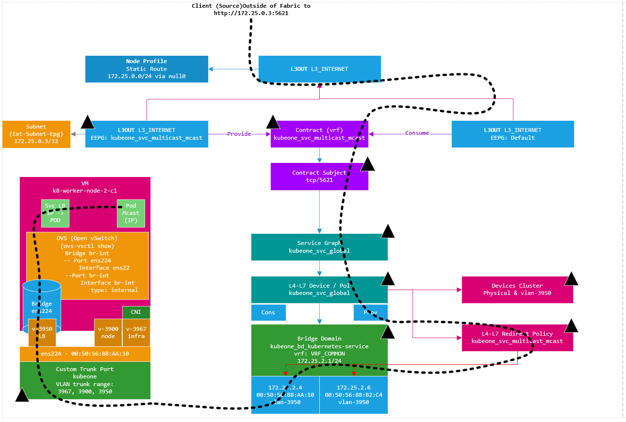
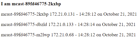
From a client external to the fabric, we use a web browser to go to http://172.25.0.3:5621

The page states which pod we have hit (‘I am mcast-89fd46775-2kxbp‘), which is running on K8 node #4 with pod IP ‘172.21.0.131’.
[root@k8-master-node-c1 mcast]# kubectl get pods -n multicast -o wide
NAME                    READY   STATUS    RESTARTS   AGE    IP             NODE                  NOMINATED NODE   READINESS GATES
mcast-89fd46775-2kxbp   1/1     Running   14         207d   172.21.0.131   k8-worker-node-4-c1   <none>           <none>
mcast-89fd46775-dbzld   1/1     Running   14         207d   172.21.0.133   k8-worker-node-4-c1   <none>           <none>
mcast-89fd46775-m2lwp   1/1     Running   0          137d   172.21.0.68    k8-worker-node-2-c1   <none>           <none>
The traffic via the L3Out, Contract and PBR service graph is not encapsulated arriving at the K8 host interface and we see the traffic enter the worker node as shown in the following pcap.

On the diagrams you may have noticed the black triangles. These indicate the components created by the CNI in ACI, they also have a little annotation icon shown within the APIC. Whats important to be aware of here it that yes they were created by the CNI but the configuration will be maintained by the CNI and if you change it, the CNI will change it back (Think Terraform Behaviour). Its a pointless pain in my view, why ? well this is where things become inflexible which I will discuss in the next post (part 2). For the moment, let me give a brief example. The contract created has a scope of VRF which means I cant use it outside of the VRF the L3Out is in, I cant even reuse the SG due to the same problem. So how do we provide access between other VRFs / IEPGs ?
Multicast Application EPG
If you recall we added an line in the mcast deployment configuration file for the CNI like this.
annotations:
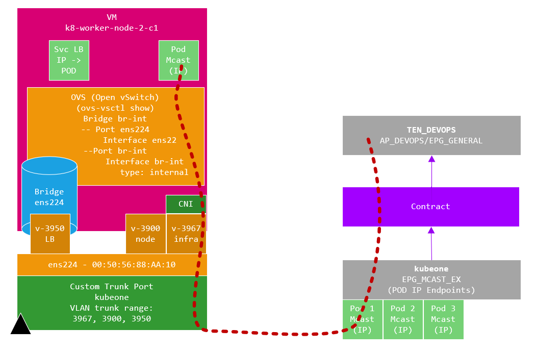
opflex.cisco.com/endpoint-group: '{ "tenant":"kubeone", "app-profile":"AP_K8_EX", "name":"EPG_MCAST_EX" }'This caused the CNI to create this EPG and as discussed, this EPG is populated with the POD endpoints through the CNI providing these over the infra VLAN in the same way a leaf switch provides connected endpoints.
Referring back to the same image of the EPG endpoints;
The mcast application Pod IPs are endpoints in this EPG. We can now create a contract (with a PBR SG) in the normal way if required to provide access to these Pods. We can use a service graph with PBR or an just insert a NLB like an F5 BIGIP to load balance over the pods. The traffic flow is the same as you would expect between leaf switches with this being transported over VXLAN as seen on the ingress to the worker node.

The traffic flow is different in that when we are targeting a Pod IP, the flow goes over the infra VLAN (3967 in my fabric) and as the CNI effectively acts as a VXLAN TEP as previously mentioned.
CNI EPG’s
The provisioning tool creates an additional 4 EPG’s in the tenant we specified in the provisioning tool configuration file, each of these are briefly discussed in the following sections.
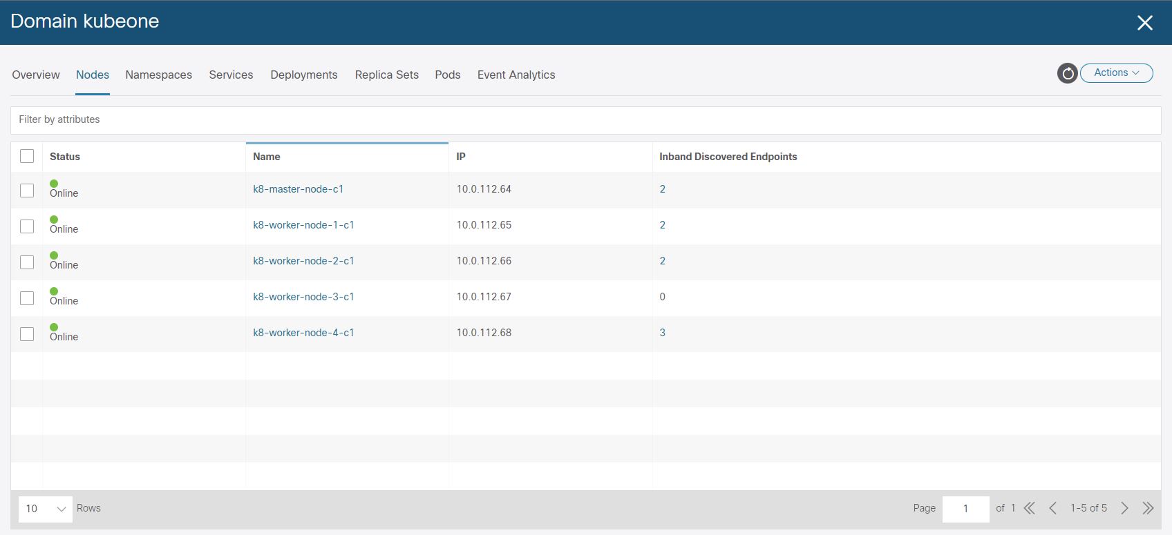
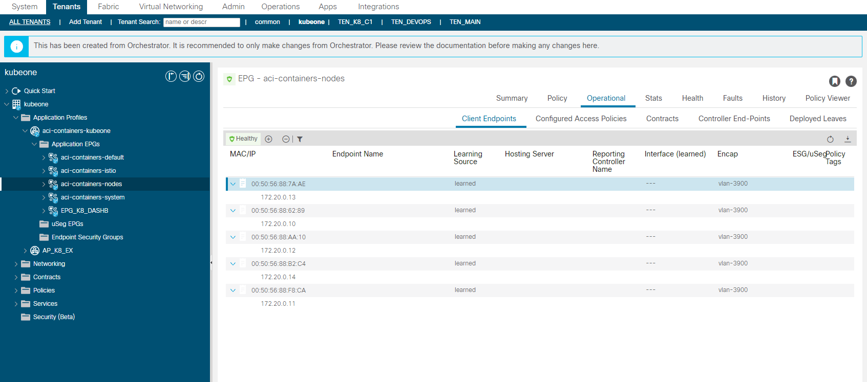
aci-containers-nodes
The aci-containers-nodes EPG contains the K8 node interfaces (sub-interface) connected on VLAN 3900, you can see from the image that each of our K8 nodes are listed with the assigned IP address. Use these addresses to manage the host (i.e. SSH), or you can add another interface for management tools etc, but this interface (V3900) must have the default route so you will have to ensure static routes are configured on the host for a new interface.
You will of course need to add a contract to this EPG to provide access via SSH etc, although the EPGs are CNI managed, they wont be reverted to the original configuration if you make changes such as adding a contract unlike the contracts and service graphs we spoke about earlier.
aci-containers-default
When we added the multicast application deployment, we specified an annotation in the configuration file which stated a Tenant|Application Profile|EPG for the multicast application to be managed from. We saw in this EPG that the multicast application Pod IP addresses (endpoints) where EPG members of, so we have the ability to apply policy (contracts) to the application pods.
If we did not specify this annotation, the Pod IPs are added as endpoints to the aci-containers-default EPG, this is true for all application deployments so they would all be in the same EPG (not what we really want). The image below shows the dnsutils K8 deployment which did not specify a specific EPG to have the Pod endpoints members of therefore they are members of this EPG instead.

aci-containers-istio
From ACI APIC 5.0(1)+, Istio is by default installed and integrated with the CNI. We did not deploy Istio here therefore we have no endpoints shown representing Istio service mesh components. By default this is is installed but you can omit the installation by adding the following to the provisioning tool configuration file.
install-istio: False 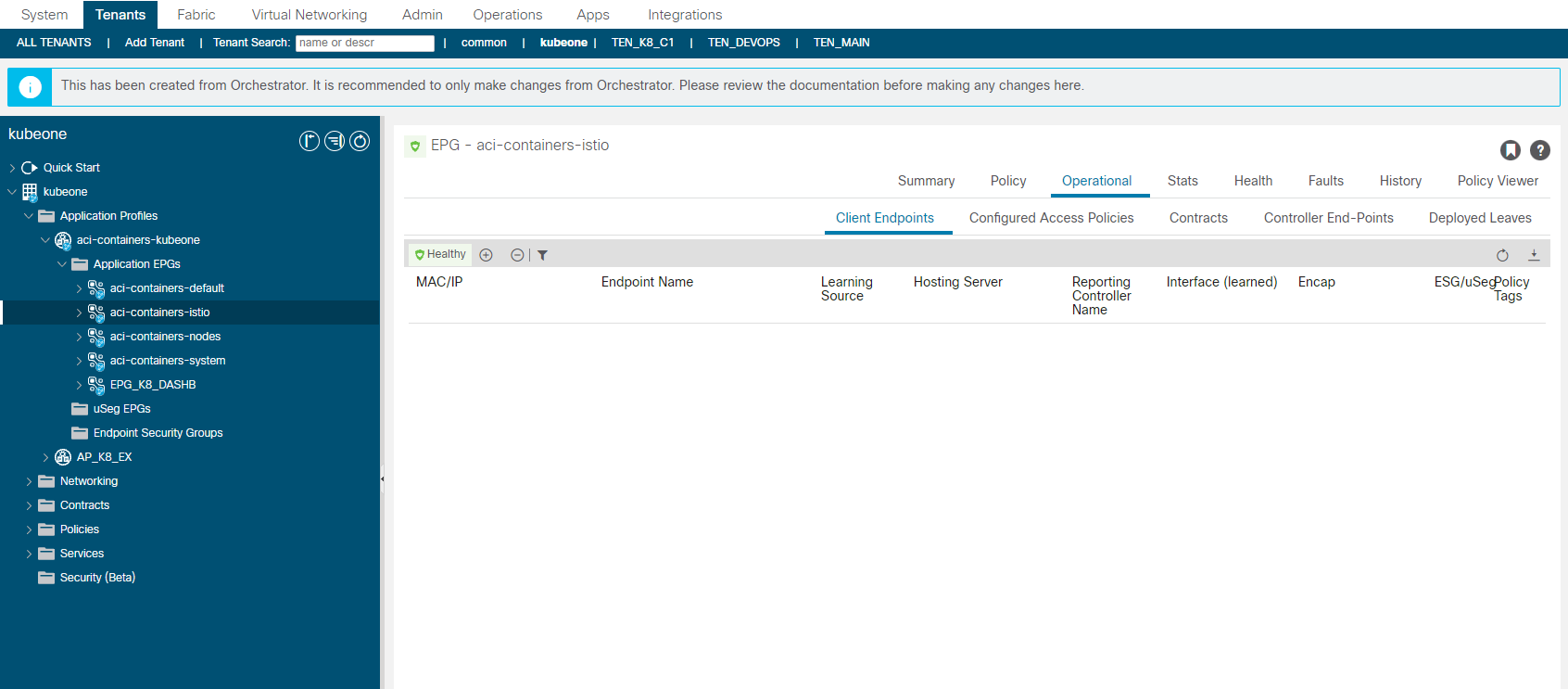
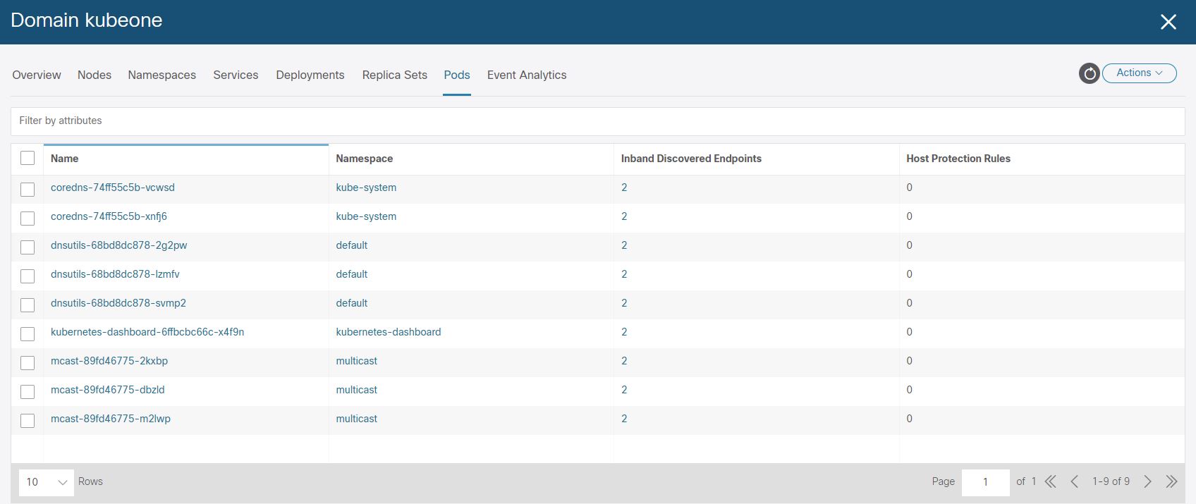
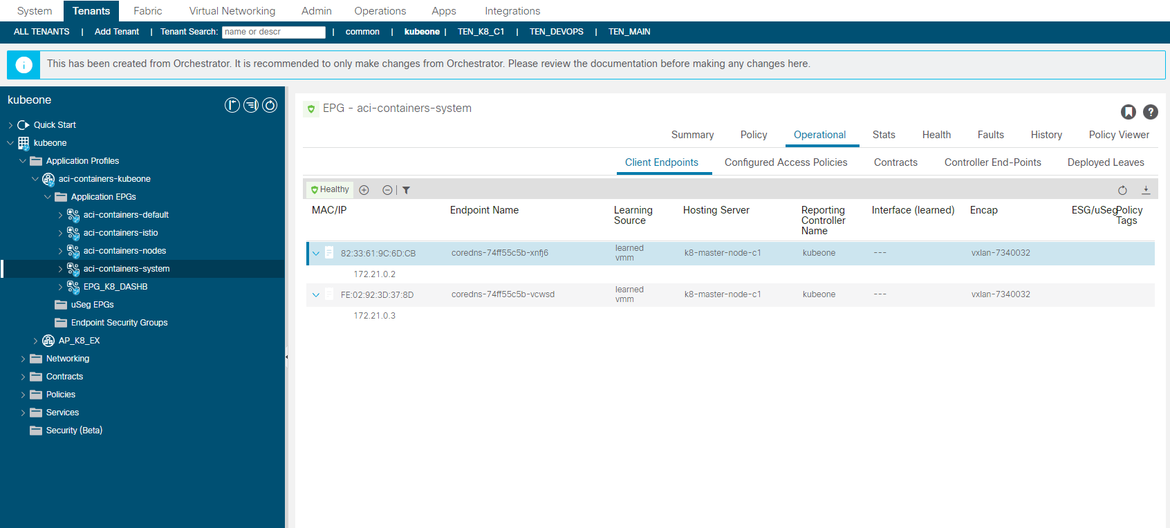
aci-containers-system
The aci-containers-system EPG contains Pod endpoints generally found in the the K8 kube-system namespace but only non core Pods. So in the example below the coredns pods are shown as endpoints but the kube-proxy, kube-controller, etcd pods are not show although they are part of the same K8 cluster namespace. CoreDNS is something you are more likely to want to access directly rather than kube-proxy for example.
Wrap Up
It feels like we kind of have two solutions/approaches to access to the K8 applications here and to me it doesn’t feel like a consistent solution, now I do like the added bonus stuff that the CNI is doing but lets look at all these pros and cons in the next post which is here.
References
Since I skimmed over a lot of the install, I have grabbed a few links which maybe helpful if you need some refreshing and some interesting reading on the CNI implementation.
Cisco ACI CNI Plugin for Red Hat OpenShift Container Platform Architecture and Design Guide – Cisco
https://phoenixnap.com/kb/how-to-install-kubernetes-on-centos
Thanks for sharing this document … Just one question ..How we will advertise 172.25.0.0/24 from ACI for external access .
As we have the 172.25.0.0/24 route ‘imported’ into the fabric via a static route, we therefore need to export the route outside of the fabric. In the scenario I presented the L3Out we are using for the ACI CNI EEPGs is the same as the L3Out for external fabric access.
For this, we have two options, we can either export the route in an EEPG with a scope of ‘Export Route Control Subnet’ or ‘export-rtctrl’ or use the default export route map. You will find this in the L3Out under the Route Map folder (name varies based on ACI version). In this folder you will find a route map called ‘default-export’, this is where we will create a match statement and apply. This route map is automatically applied to all nodes in the L3Out so you do not need to apply it yourself.
1. Click ‘+’ to add a new context
2. Give the context a name. e.g. ROUTE_CTL_CTX_0
3. Click ‘+’ to create a new ‘Associated Match Rule’
4. Select ‘Create Match Rule for a Route Map’
5. Name the match rule
6. In ‘Match Prefix’ click ‘+’ to add the prefix.
7. In IP enter 172.25.0.0/24
8. Click ‘OK’s all the way back.
You should now be automatically exporting (advertising) that route out of the fabric providing you have external dynamic route peering setup.