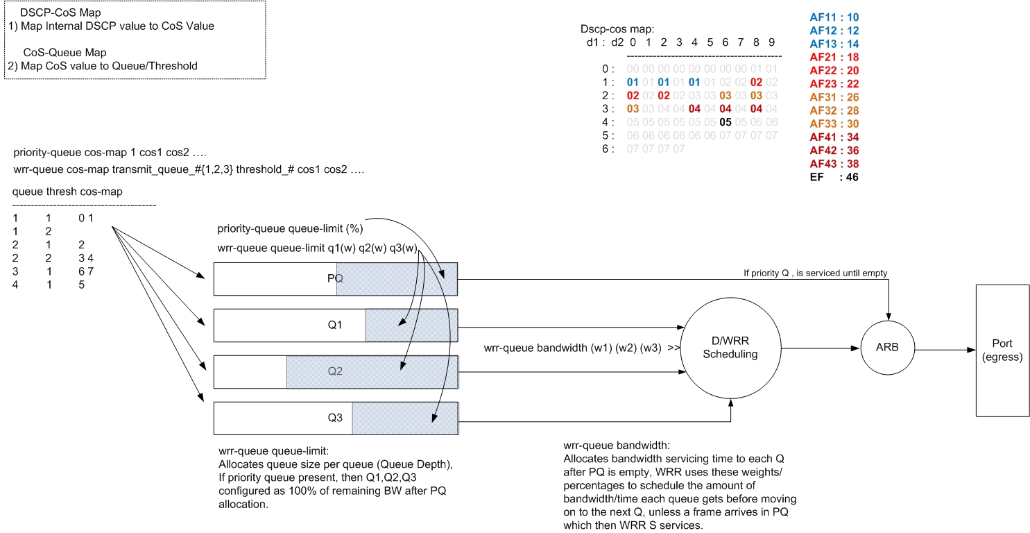
PFC Egress Flow
The following diagram shows the process of egress showing effecting commands vs. the area of concern. A 1p3qxt card has been used in the example below, the ‘xt’ in the queueing definition could be 4 or 8 thresholds although is irrelevant for this example as WRED is not discussed here.
The priority queue id is always number 1 in the ‘priority-queue cos-map q-id cos# ‘ command, when using the command ‘show queueing interface’ and looking at the cos-queue mappings the priority queue is shown as queue 4 as shown in the output in the diagram below.
Egress Maps
The internal DSCP value is mapped to a internal CoS value first using the dscp-cos map (‘show mls qos maps’), the internal CoS value is then used to map the frame to a queue, use ‘show queueing interface’ to see this mapping. The (internal) DSCP to CoS map shown in the diagram below is the default, the relevent values for DSCP AF and EF have been highlighted and other values grayed out for clarity.
IP Packet DSCP Egress Value
By default the Internal DSCP value is used to modify the IP ToS (IPP) bits in the underlying IP packets. This is done because the Internal DSCP value may have been modified from when it was originally derived from the incoming packet (derived from DSCP, CoS or IPP – this is based on ‘mls qos trust’ command on ingress). If this behaviour is not desired then use the global command ‘no mls qos rewrite ip dscp’. This feature is called the “Disable DSCP Rewrite” feature. This will prevent the PFC/DFC from rewriting the IP Packet IPP on egress therefore leaving the IPP/DSCP value intact being the same as it was on ingress to the switch.
Ethernet Frame 802.1p (CoS) Egress Value
