Cisco ACI Static Port Assignment Methods
There are a few ways to assign Cisco ACI leaf switch ports for use by endpoints in endpoint groups each with its own pros and cons. This post discusses the different static methods and what to consider in using each method. We have both static and dynamic assignment of ports to EPG’s, this post focuses on the static methods.
Understanding the Managed Object Model
We will briefly cover the relevant parts of the APIC MO (Managed Object) Model, this will help provide some context to the configuration methods we describe below and always helps to have a diagram to refer to which follows. The diagram shows the related objects when configuring switches, ports and EPGs to work together. Each blue node represents a configurable MO in the APIC, the green boxes indicate how the APIC allows configuration, a green box represents a “gui screen” or GUI configuration task on the APIC where multiple MO’s are configured on the same screen / within the same task.
This should help bridge the gap between the real MO model and the way the APIC GUI provides the configuration of these objects. One exception in the EPG (in red) this is shown as a general object with the actual relationship MO’s between the EPG and Physical Domain & AEP shown in the red boxes next to the connections between these objects.

The diagram shows the EPG has two configurable paths from itself to the configured switches and ports through a chain of MO’s. The arrow heads indicate which way the objects are related (from source to a target relation or child of a source), this is evident in the MO configuration or even within the APIC where you configure an association with another object. For example, using the APIC GUI, you configure the relationship between the AEP and the Physical Domain from the AEP configuration “screen”, under the hood any related (not child) MO’s have either a Rt (target) or Rs (source) child which points to the related object.
The Leaf Interface Policy Groups MO has two concrete types with the second have two sub-types dictated by the “lagT” attribute.
- The first type is “infraAccPortGrp” which is used for access ports, access ports in this policy group context means no Port Channel (PC) or Virtual Port Channel (vPC), so singularly connected devices to the fabric.
- The second type is “infraAccBndlGrp”, a bundled group. This is for a single instance of a PC or vPC connected device , the “infraAccBndlGrp” attribute “lagT” has two sub-options, “link” or “node” where “link” defines a PC configuration and “node” defines a vPC configuration.
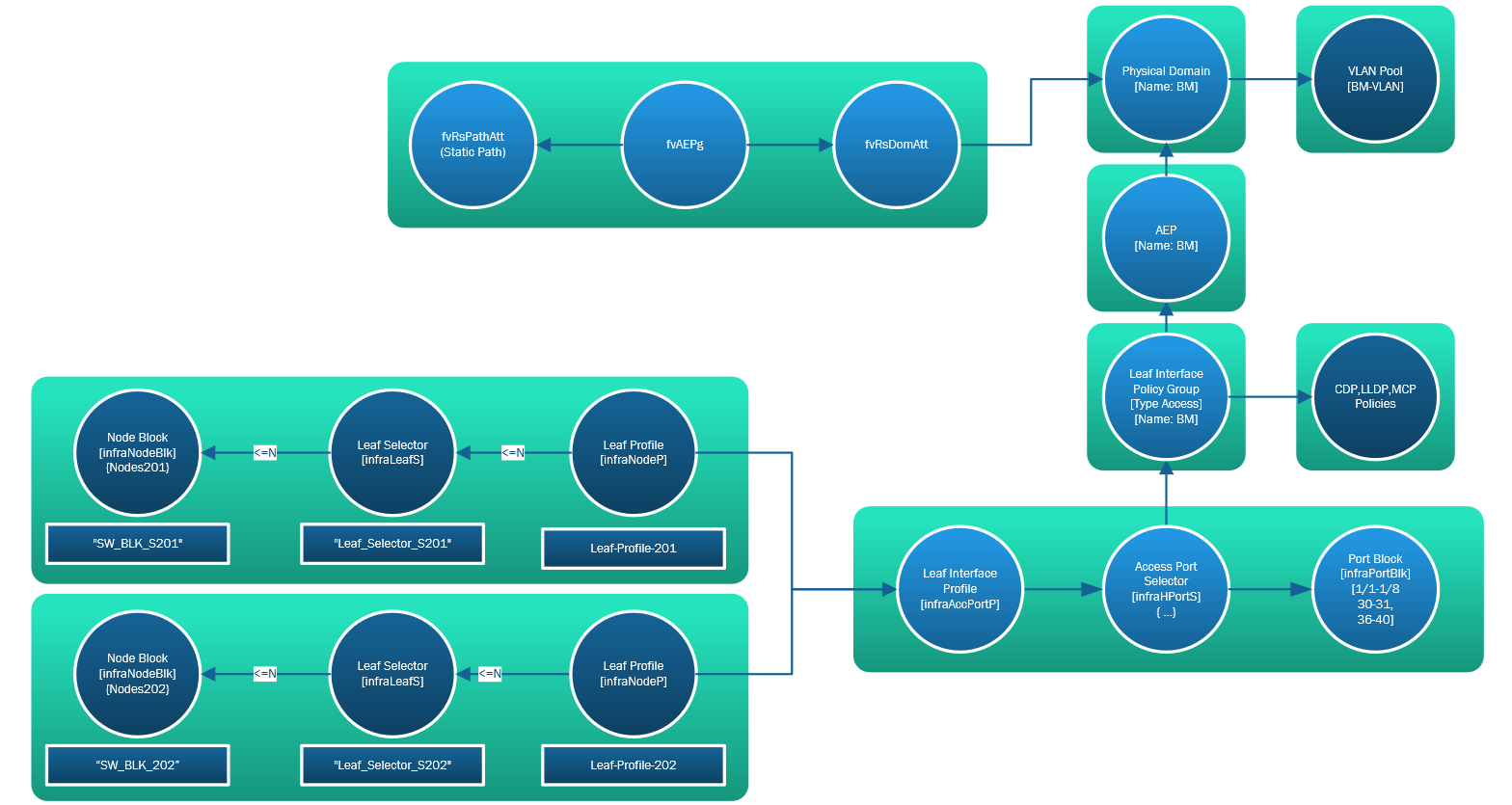
Static assignment of selected ports with VLAN ID via EPG
This is the common and recommended way to assign ports statically to an EPG on a particular VLAN. This method uses the full MO chain of an EPG connected to a Physical Domain associated with a AEP>Interface Policy Group>Leaf Interface Profile>Leaf Profile chain. This is shown in the following diagram. Assigning static ports within a EPG should be done for a small number of ports, managing a large number of static ports can be difficult. You should use static assignment for infrastructure ports, an example of this would be a port which provides a bridge to a legacy switched network which runs MST spanning tree. VLAN 1 must be the native VLAN in this case. MST uses VLAN 1 for all BPDU’s & TCN’s for all VLAN’s it is running on. It is a good idea to use the static port method to tie this port down to VLAN 1 and to 801.1p and not to rely on any of the following methods. The number of static port entries can get quite large on a medium to large fabric and the following options may seem more attractive but keep in mind that ACI provides an excellent REST API which when you find you are having trouble just managing via the GUI, its time to be using the API to manage your fabric after all this is one of the best features of ACI having a stable and reliable API.
Static assignment of all EPG endpoints to AEP with VLAN ID
This method enables the assignment of all endpoints in the EPG on the same VLAN without the use of the static port method previously described. In this method we statically assign the EPG in the AEP using the “Application EPG’s” section and define a VLAN ID and a port trunk type (access, dot1q, dot1p) as part of that assignment. The domain assignment in the EPG is also required to prevent faults being raised by the APIC. The configuration uses the entire MO chain shown in the following diagram where ports are assigned via the Leaf & Leaf Interface Profiles.
Note that we are assigning a VLAN ID and a port type (access, dot1q, dot1p) for all endpoints in this EPG. This means that if we configure an EPG in an AEP with a VLAN ID of 5 and a port trunk type of access, that the APIC will expect that all these endpoints will have untagged frames. Keep in mind that an AEP effectively provides access to a defined group of switches & ports to connected EPG’s, this implies that only one EPG connected to the same AEP can use the “access” port type, if we have two EPGs assigned to an AEP with different VLANs but both with the “access” (untagged) type, how does the APIC know which BD/EPGs the ingress traffic belongs to ? There are also differences in how the different generation of switches (G1/G2 {EX}) behave with an “access” and a “dot1p” type. G2 generally see these as the same.
Generation 2 switches, or later, do not distinguish between the Access (Untagged) and Access (802.1p) modes. When EPGs are deployed on Generation 2 ports configured with either Untagged or 802.1p mode
Read this link this for more info.
Assignment of the EPG to the physical domain must be completed, leaving this step out may leave you with a working configuration but faults will be raised by the APIC due to lack of domain assignment to the EPG – so assign the domain to the EPG even though it may seem to work without.
This method is not recommended or a best practice, you may find corner cases where this may help during a migration but certainly don’t plan on using this as a long term strategy.
Leaf Interface Policy Group Connectivity Filters
Although not strictly a method of assigning ports I wanted to cover an option called “Connectivity Filters”. This option appears in a Leaf Interface Policy Group (Access, vPC or PC) when an AEP has been assigned. When we have Interface Selectors (and therefore Switch Selectors) assigned to the Leaf Interface Policy Group we may have a group of ports (e.g. 1/1-6) on two switches (101, 102) assigned. The connectivity filters allows you to filter out the switches & ports you want to use from the assigned group of switches & ports in the leaf and interface selectors. Why would you do this ? Who knows?, if we wanted to change the switches & ports assigned to a interface policy we would change this in the interface selector which is directly bound to the policy group. Its possible that we have a number of switches in a switch profile (101 & 102) bound to the interface profile and we want this policy to use only the ports on switch 101. This could mean you probably need to revisit your design in terms of how you are using objects for switches and interfaces.
In short, don’t use this method unless you really have no choice, in addition it is rumored that Cisco may deprecate this feature in future versions (at this time of writing 3.0[2h] has just been released and the feature still exists).
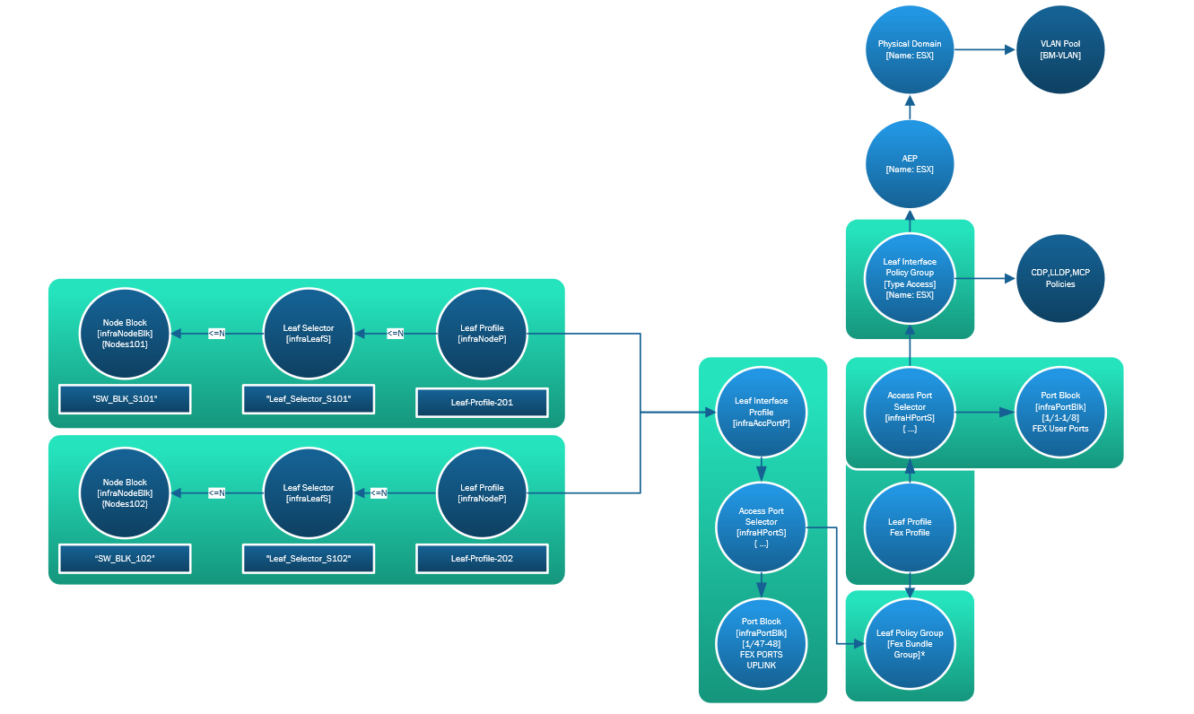
FEX Managed Objects
And finally, in case you are wondering where the FEX MO’s fit in all this, the following diagram has the FEX MO’s included.
The objects created are a Leaf Profile (for the leaf switch connected to the FEX) which references a new Leaf Interface Profile (for the interface(s) on the leaf switch connected to the FEX), so far this is the same as defining a leaf switch and port, we usually at this point then assign an Interface Policy Group for each set of ports we define in the selector, but instead of referencing an Interface Policy Group we select a FexBundle which is the connector between the leaf and the FEX ports to be used.
A FEX Profile created in “Leaf Profiles” provides a bi-directional link between the ‘leaf switch(es) FEX connected port(s)‘ and the ‘FEX Access Port Selectors’, these being the host ports for device connectivity (servers, hosts, etc). Within the FEX profile we select the FEX ports we want to use and select a Interface Policy Group as usual to connect these ports to.